Generally, the maximum allowable current of a three-phase direct meter is 120A, and the rated voltage is 380V. If the power load exceeds 120A, or the voltage exceeds 400V, the current and voltage transformer should be used to increase the meter scale. In the selection of transformers, the general measurement should use the accuracy of 0.5, or higher level of 0.5S or 0.2, for the price, of course, increase the transformer to increase investment, mainly to see your capacity How large and the requirements for measurement are considered;
From the perspective of measurement principle and composition, there is no essential difference. Meters with transformers generally have a rated current range of 5A and a short-term overload of 6A. The meter directly measured generally has a large rated current range and a strong overload capability.
It can be directly converted by the formula.
1, the current transformer meter scale calculation formula: the actual primary current = secondary current X transformer ratio ratio / 5 turns.
2, the power meter degree = the number of words X voltage change ratio X current ratio / 5 turns.
3, for example, the current transformer ratio is 1500/5 (the transformer name brand), the main line is 5 turns, then the transformer becomes 300/5, then if the meter goes 5 degrees, the actual power It should be 300 degrees. If the meter goes 1 degree, the actual power is 60 degrees.
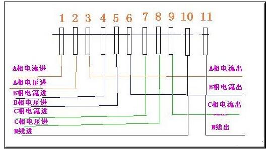
Three-phase four-wire electric meter wiring diagram / wiring method
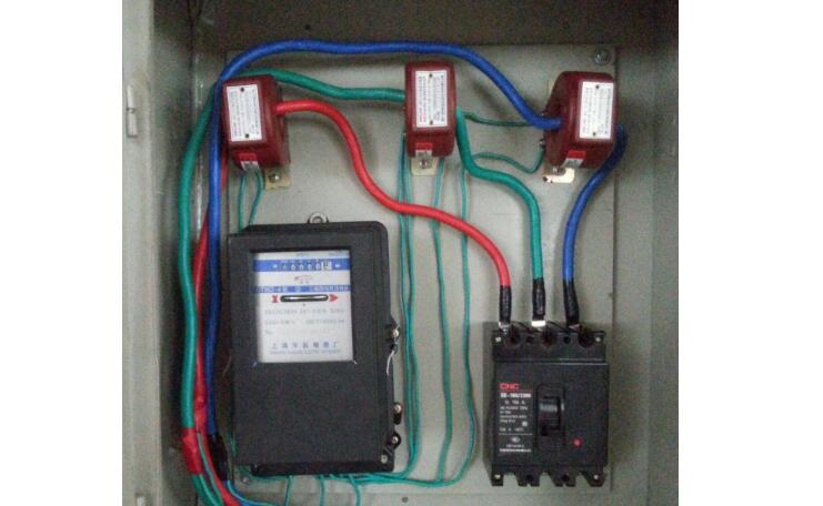
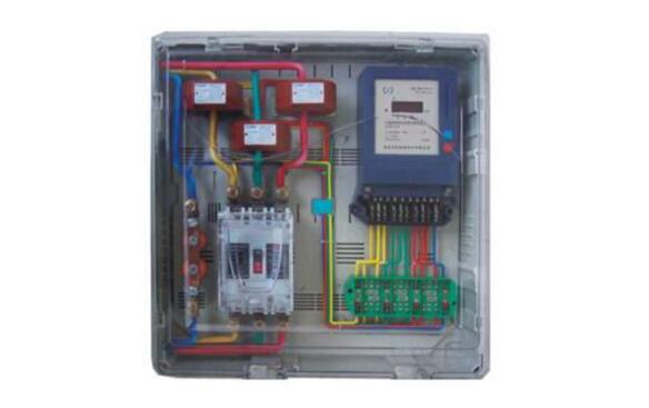
Turn over the terminal cover and you will see the wiring diagram of the three-phase four-wire meter. 1, 4, 7 are connected to the secondary side S1 end of the current transformer, that is, the current incoming end;
3, 6, 9 connected to the secondary side S2 end of the current transformer, that is, the current outlet end;
2, 5, 8 respectively connected to the three-phase power supply;
10, 11 is the zero terminal. For safety, the current transformer S2 should be connected and grounded.
Note that the current measurement samples of each current transformer must be in phase with their voltage samples, that is, 1, 2, and 3 are a group; 4, 5, and 6 are a group; and 7, 8, and 9 are a group.
Three-phase four-wire electric meter wiring diagram without current transformer 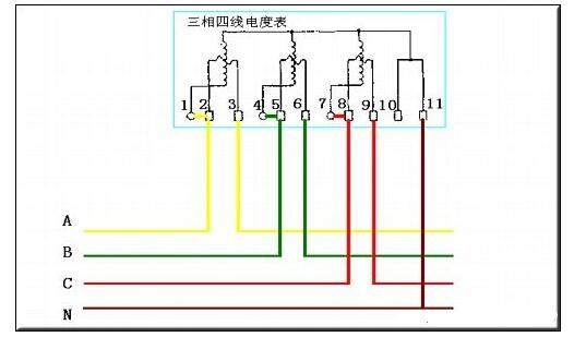
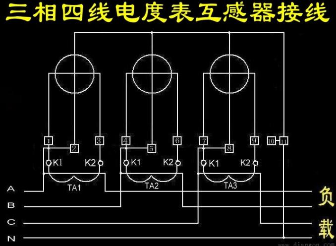
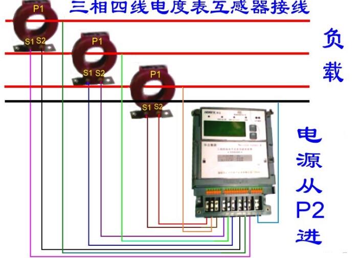
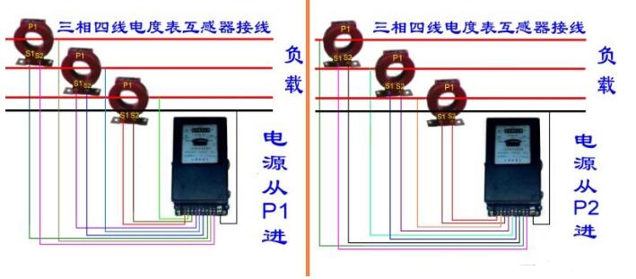
Three-phase four-wire meter wiring with current transformer 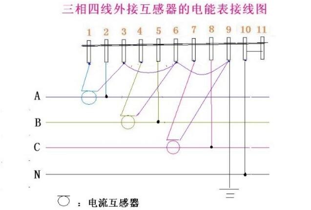
Recommended reading: What happens when the transformer is reversed?
The Description of 2G/3G/GSM/4G/5G Antenna
Frequency of 5G Antenna: 885-900mhz/1800-2170mhz
2G/3G/GSM/4G/5G Antenna is mainly used for communication, which can enhance the signal of mobile phone, computer and wireless Internet. 2G/3G/GSM/4G/5G Antenna has indoor and outdoor, Outdoor Antenna is waterproof, sun protection, lightning protection , Corrosion.
The Picture of the Description of 2G/3G/GSM/4G/5G Antenna:


2G Antenna,3G Antenna,GSM Antenna,4G Antenna,5G Antenna
Yetnorson Antenna Co., Ltd. , https://www.xhlantenna.com