An oscilloscope is an electronic measuring instrument that converts an analog electrical signal into an image of a waveform display signal. Through the measured circuit waveform, we can observe the amplitude, phase, and frequency of the waveform, and analyze and compare the waveform. Although there are many types and models of oscilloscopes, the functions and operations of the oscilloscope are basically similar. The following describes the use of general-purpose oscilloscopes.
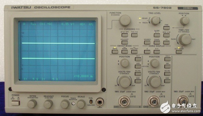
First, the panel introduction
1. Brightness and focus knob
The brightness adjustment knob is used to adjust the brightness of the light trace (some oscilloscopes are called “luminanceâ€), and should be used properly when used. If it is too bright, it will easily damage the oscilloscope. The focus adjustment knob is used to adjust the focus (thickness) of the trace. It is better to use the graphics when using.
2. Signal input channel
Commonly used oscilloscopes are mostly dual-track oscilloscopes. There are two input channels, channel 1 (CH1) and channel 2 (CH2). You can connect the oscilloscope probe separately, ground the oscilloscope case, and insert the probe into the part to be tested for measurement. .
3. Channel selection button (vertical mode selection)
A common oscilloscope has five channel selection keys:
(1) CH1: Channel 1 is displayed separately;
(2) CH2: Channel 2 is displayed separately;
(3) ALT: two channels alternately displayed;
(4) CHOP: two-channel intermittent display, used for double trace display when the scanning speed is slow;
(5) ADD: Signal superposition of two channels. In the maintenance, select channel 1 or channel 2 as much.
4. Vertical sensitivity adjustment knob
To adjust the vertical deflection sensitivity, adjust the position of the knob according to the amplitude of the input signal, and multiply the value indicated by the knob (such as 0.5V/div, which means the vertical direction is 0.5V per division) multiplied by the measured signal in the vertical direction of the screen. The number of cells is the amplitude of the signal under test.
5. Vertical movement adjustment knob
It is used to adjust the position of the signal trace of the signal under test in the vertical direction of the screen.
6. Horizontal scanning adjustment knob
To adjust the horizontal speed, adjust the position of the knob according to the frequency of the input signal, and indicate the value of the knob (such as 0.5ms/div, which means that the horizontal direction is 0.5ms per division), multiply by the measured signal for one cycle, that is, The period of the signal is obtained and can also be converted into a frequency.
7. Horizontal position adjustment knob
It is used to adjust the position of the signal trace of the signal under test in the horizontal direction of the screen.
8. Trigger mode selection
Oscilloscopes usually have four trigger modes:
(1) Normal state (NORM): When there is no signal, there is no display on the screen; when there is a signal, it displays a stable waveform in conjunction with the level control;
(2) Automatic (AUTO): When there is no signal, the light trace is displayed on the screen; when there is a signal, the stable waveform is displayed in conjunction with the level control;
(3) Television field (TV): used to display TV field signals;
(4) Peak auto (PP AUTO): When there is no signal, the trace is displayed on the screen; when there is a signal, the stable waveform display can be obtained without adjusting the level. This method is only used in some oscilloscopes (such as the CALTEK Caltec CA8000 series oscilloscope).
9. Trigger source selection
There are two types of oscilloscope trigger sources: internal trigger source and external trigger source. If an external trigger source is selected, the trigger signal should be input from the external trigger source input, which is rarely used in appliance repair. If the internal trigger source is selected, channel 1 (CH1) or channel 2 (CH2) is generally selected and should be selected according to the input signal channel. If the input signal channel is selected as channel 1, the internal trigger source should also select channel 1.
Second, the measurement method
1. Measurement method of amplitude and frequency (take the calibration signal of test oscilloscope as an example)
(1) Insert the oscilloscope probe into the channel 1 jack and place the attenuation on the probe in the "1" position;
(2) The channel selection is placed in CH1, and the coupling mode is placed in the DC file;
(3) Insert the probe probe into the small hole of the calibration signal source, and the light trace appears on the oscilloscope screen;
(4) Adjust the vertical knob and the horizontal knob to make the waveform of the screen display stable, and place the vertical fine adjustment and horizontal fine adjustment in the calibration position;
(5) Read the waveform of the waveform in the vertical direction, multiply by the indication value of the vertical attenuation knob to obtain the amplitude of the calibration signal;
(6) Read the waveform as the number of cells in each cycle in the horizontal direction, multiply by the indication value of the horizontal scanning knob to obtain the period of the calibration signal (the reciprocal of the period is the frequency);
(7) The general calibration signal has a frequency of 1 kHz and an amplitude of 0.5 V. It is used to calibrate the internal oscillator frequency of the oscilloscope. If it is not normal, adjust the corresponding potentiometer of the oscilloscope (internal) until it matches.
2. Oscilloscope application example (taking the measurement of 788 mobile phone 13MHz clock pulse as an example)
The 13MHz clock signal in the mobile phone is a necessary condition for power-on, so it is often necessary to measure whether there is a 13MHz clock signal during maintenance. Proceed as follows:
(1) Turn on the oscilloscope, adjust the brightness and focus knob, so that a horizontal bright line with moderate brightness and good focus is displayed on the screen;
(2) Calibrate the oscilloscope as described above, and then place the coupling mode in the AC file;
(3) Clip the grounding clamp of the oscilloscope probe to the grounding point of the mobile phone circuit board, and insert the probe into the first foot of the 788 mobile phone CPU;
(4) Turn on the power of the mobile phone, press the power button, adjust the vertical scanning water and the scanning knob to observe whether there is a stable waveform on the screen. If not, generally there is no 13MHz signal.
Compression Driver,Tweeter Driver Unit,Compression Driver Speaker,High Frequency Compression Driver
Guangzhou Yuehang Audio Technology Co., Ltd , https://www.yhspeakers.com