Six, troubleshooting guidance
1. Communication network failure
(1) Poor contact of the communication connector will cause a communication failure. After confirming that the failure has occurred, you can use a special tool to redo the connector.
(2) Since each communication unit has an address setting, during communication maintenance, confirm whether the address settings of the network card, main control card, and data forwarding card are correct.
2. Field equipment failure
The operator should switch the automatic control circuit to manual, and the bypass valve should be used when the valve is repaired.
(1) The corresponding control circuit, control program, and interlock should be immediately switched to manual operation, and the system maintenance personnel should immediately replace the faulty card, and confirm that the fault is eliminated before putting the system into automatic operation again.
(2) Before replacing the card, set the address, power distribution, redundancy and other switches or jumpers to the original card position (see "Hardware Manual").
(3) For non-redundant output card failures, the valves and equipment corresponding to the failed card cannot be operated on the DCS side. The on-site operator must be notified to perform on-site operations. DCS operations can only be performed after the failure is eliminated.
4. When an abnormal interruption occurs in the factory's power supply system, the DCS should be powered off according to the system power-off procedure after handling the moving equipment, valves and other instrument equipment according to the process requirements.
5. When the control system fails and causes the system to be paralyzed (this situation is rare), an accident plan must be formulated in advance.
Seven, configuration modification and download guidance
1. Basic principles of configuration modification
Before the configuration file is modified, the current configuration file must be backed up for emergency recovery. The modification of the configuration file must be carried out on the engineering station.
2. Configuration modification during production
In the production process, the DCS configuration needs to be modified for various reasons to achieve a good monitoring effect. The modified content needs to be effectively distinguished during the modification process:
(1) Only add or modify the overview (or flowchart, report, trend page, control group, data list, user authority, secondary calculation, voice alarm, operation group, custom key), modify the tag unit (or bit No. Note) and other operations, after completing the above operations, complete the compilation and transfer to each operating station and reload the configuration, without downloading.
(2) To add or delete the card, add or delete, change the tag number, or modify the tag range (or alarm information), it needs to be downloaded.
When using the SP243X, XP243, FW243L three main control cards, if the process device is in production state, the download work cannot be performed, and the download must be performed when the process device is in the parking state, otherwise it will have a certain impact on production;
If the XP243X, FW243X, FW247 master control card is used, if the modification of the card and tag does not involve the control program, the download can be performed when the process device is in production; if the control program is involved, the related control program After deactivation (such as interlock cancellation, automatic switch to manual), the download can be started.
(3) The modification of the control program requires configuration download.
When using the SP243X, XP243, FW243L three main control cards, if the process device is in production state, the downloading work cannot be carried out. It must be downloaded when the process device is in the parking state, otherwise it will have a certain impact on production;
If you use the XP243X, FW243X, FW247 master control card, you need to disable all control programs related to the control program (such as interlock cancellation, automatic switching to manual) before downloading.
(4) Adding or reducing the cage to a certain control station must be carried out when the process device is in a stopped state. It is strictly forbidden to modify and download the configuration when the process device is in the production state. It is important to note that if you add or delete content in the middle of the existing card address or in the middle of the existing custom tag, online download will cause a large amount of data inconsistency, and it should be avoided.
3. Precautions when downloading during the production process
(1) For online download, choose a stable production time, and avoid sequential control switching, accurate measurement of cumulative amount, etc., confirm the removal of important interlocks before downloading, and temporarily switch important circuits to manual operation.
(2) When downloading, all control programs and control loops must be switched to manual; cut off the interlock.
(3) Before and after the configuration file is modified and downloaded, the modified content should be verified accordingly to ensure its correctness.
(4) After the configuration is downloaded, the configuration must be transmitted in time to ensure that the configuration of the engineer stations of each operation station is consistent.
(5) Operation process of online download during production process:
Replace the configuration on the operating directory of the field engineering station with the new configuration that has been changed.
Open the secondary calculation software, and then exit, after the configuration is compiled and passed, start the real-time monitoring software.
Compare the software interface data before and after the modification with the adjacent operator station, adjust the loop opening, PID parameters, the positive and negative effects of the regulator, and then proceed to the next step after confirming that it is correct.
Contact the process operator to release the interlock of the system on the interface to ensure that the interlock will not malfunction, and switch the adjustment loop to manual, and switch important instruments and electrical equipment to on-site operation.
Download the configuration. After the download is complete, set the initial value for the newly modified and added program in time.
Contact the process operator to test the newly modified and added program.
The technician confirms that the PID parameters, temperature, liquid level, pressure, etc. on the flow chart are displayed normally. After confirming that they are correct, they are ready to put in the interlock to restore the automatic control of the regulating loop, and the on-site operators will withdraw.
After the download is complete, all parties confirm.
4. Changes and downloads in non-production state
(1) If there are many configuration changes that do not meet the online download regulations, you can modify the download when the process is stopped.
(2) After downloading, the program must be debugged immediately, and the programs, valve positions, and parameters must be checked to see if they are normal. Only after checking and confirming that there is no error can drive again.
8. System upgrade guidance
Precautions:
(1) The original configuration and parameters must be backed up before upgrading.
(2) The process production must be in a shutdown state during the upgrade, and the relevant upgrade instructions must be strictly followed.
(3) After upgrading, you must check and confirm whether the control loops and parameters are normal.
(4) The new version of the software and installation instructions must be copied to each upgraded computer in time; the original software backup on the hard disk of each computer must be deleted; the old version of the installation CD must be destroyed or the label must be invalidated.
Nine, UPS maintenance guidance
1. UPS usage environment
(1) The computer room where the UPS is located should maintain a constant temperature, which is recommended to be controlled at 20~25℃; the battery should be at 5℃~30℃;
(2) The UPS room should be ventilated, and there should be no obstructions at the fan; UPS and batteries should not be placed in a sealed structure to avoid damage to the machine and personal injury;
(3) The surface of the UPS should be kept clean and dry.
2. Correct use of UPS
(1) The operation must be carried out in strict accordance with the correct turn-on and turn-off sequence to avoid too large fluctuations in the output voltage of the UPS due to sudden loading or de-loading;
(2) It is strictly forbidden to turn off or turn on the UPS frequently. Generally, it is required to wait at least 6 seconds before starting the operation after it is turned off, otherwise the UPS may enter the "start failure" state, that is, enter the state of no mains input and no inverter output;
(3) UPS is forbidden to be overloaded, and the maximum load is best controlled within 80%;
(4) The UPS switch is a do not move operation, please press and hold for more than one second;
(5) Lightning strikes are the natural enemy of all electrical appliances, so care must be taken to ensure the effective shielding and grounding protection of the UPS;
Note: When the Shante UPS fails, you need to check the indicator on the front panel according to the requirements of the manual: whether all the switches are activated; whether it is in the on state or the bypass state (note that the UPS also makes a sound in the bypass state ); Whether there is mains input; whether the mains switch on the back of the UPS is turned on; whether the battery box switch of the UPS is closed; sometimes the machine beeps for a long time and the red light is on, indicating that the UPS is faulty. At this time, the UPS is not broken because it is overloaded. Shut down and remove the load. Restart it and the UPS will work normally.
3. Correct use of batteries
(1) In the same UPS, batteries of the same brand, model and specification must be used;
(2) Do not use the battery in a fire or heating place;
(3) During the installation process, if the light is dim, do not use fire source lighting to avoid explosion and fire;
(4) Metal installation tools such as torque wrenches and pliers should be wrapped with vinyl tape. Do not reverse the polarity of the battery during installation, otherwise it will cause fire and damage to the UPS charger;
(5) The battery generally has a service life of 3-4 years and needs to be replaced regularly; the replacement period is three years at 25°C, 2.5 years at 30°C, and 2 years at 40°C;
(6) If there is no power outage for a long time, the battery needs to be discharged manually, usually once every three months (discharge according to the time of the backup battery); the continuous discharge of the battery should not exceed the maximum value allowed by the manual, and it should be immediately after discharge Charging, do not store without electricity;
(7) When there is a power failure, you need to use a multimeter to measure the voltage of a set of batteries (preferably once every 5 minutes). If it drops quickly, prepare for shutdown to avoid deep discharge of the battery; if the host sounds an alarm, you should immediately Shutdown
(8) The set voltage for battery charging should be within the specified range of UPS. Exceeding the range may easily cause damage to the battery, decrease in capacity, and shorten life.
Note: For the specific maintenance of different types of UPS, please refer to the manual of each UPS manufacturer.
10. Introduction to Calibration and Maintenance
1. Introduction to the use of X219 universal process calibrator
X series process calibrator is a battery-powered hand-held instrument. Function keys and digital keys coexist. It is easy to operate. It can measure and output multiple signals at the same time. It supports voltage, current, resistance, frequency, thermocouple, thermal resistance, etc. Various signal types, can use 4 AA Ni-MH or Ni-Cd rechargeable batteries, can also use alkaline batteries, low maintenance cost, mainly used in industrial field and laboratory signal measurement and calibration, can be used for DCS cards Maintenance, process instrument fault diagnosis, calibration, verification.
The X series process calibrator fully adopts international standards such as EN55022 and EN55024, and represents the current first-class level in terms of appearance design, software and hardware functions, and working reliability.
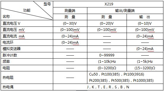
The highest accuracy of the X series process calibrator is ±0.015% FS, and the accuracy of the X219 universal multifunctional process calibrator is ±0.02% FS. The functions of the X219 universal process calibrator are shown in Table 1.
Table 1 List of measurement and output functions
X219 has the following main features:
(1) Miniaturized design, easy to carry and hold;
(2) Function buttons and digital buttons coexist, easy to operate;
(3) Battery power display, automatic shutdown when power is insufficient;
(4) The white LED backlit LCD screen can be used normally in low-light environments;
(5) Measure five-digit display, and automatically adjust the display resolution according to the signal size;
(6) Smart flash jack prompt to avoid misoperation;
(7) The left measurement terminal is completely isolated from the right measurement/output terminal;
(8) It has both left measurement and right measurement/output functions, two inputs or one input and one output can be performed at the same time;
(9) The signal measurement/output has the function of clearing;
(10) 2/3/4 wire system is optional for resistance measurement;
(11) It has output lead resistance compensation function during resistance output;
(12) Automatic step and ramp output;
(13) Frequency signal output with adjustable amplitude (0-22V);
(14) When outputting or measuring thermocouple signals, it can automatically perform cold junction temperature compensation without calculation;
(15) The cold junction ambient temperature compensation method can be manual or automatic;
(16) Built-in 90 international temperature scale graduation table;
(17) Switching between Celsius and Fahrenheit temperature scales;
(18) Measure or simulate thermoelectric potential values ​​below 0℃;
(19) When measuring thermocouple or thermal resistance signal, the temperature value and voltage or resistance value can be displayed simultaneously, no need to check the index table again;
(20) 4 AA Ni-MH batteries or Ni-Cd rechargeable batteries can be used, and alkaline batteries can also be used, with low maintenance costs;
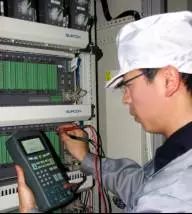
2. Maintain DCS cards
The I/O cards supporting DCS include current signal input card, voltage signal input card, thermal resistance signal input card, level signal input card, pulse input card, current signal output card, all of which can use X219 universal process calibration The tester is used for fault diagnosis and positioning, and the card can be quickly tested for linearity through the automatic stepping and ramp output functions of the X219.
3. Drive and maintain the actuator
X219 supports type II and type III analog current output and has strong driving capability. Using X219's analog current output function, it can be used to drive field execution structures, such as electrical converters, valve positioners, etc.

4. Maintain the isolation barrier
X219 can simulate two-wire transmitter output (4~20) mA current signal. Using X219's analog transmitter function, the input and output signals of the isolation barrier can be displayed on the same screen. Only one process calibrator is used. The isolation barrier can be adjusted and maintained conveniently, quickly and simply on site, without external power supply and other equipment.
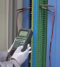
5. Maintain the calibration transmitter
X219 can be used to calibrate various transmitters, and the operation is simple and fast. In the left figure, X219 simulates the output of a thermocouple and measures the output current from the transmitter. The lower part of the LCD screen displays the output value of the analog thermocouple, and the upper part displays the output current of the transmitter.

Plug-In Connecting Terminals,Insulated Spade Terminals,Cable Connector Double Spade Terminals,Vinyl-Insulated Locking Spade Terminals
Taixing Longyi Terminals Co.,Ltd. , https://www.longyicopperlugs.com