Because of aesthetics, maintenance, cost, and hygiene, touch screen technology has begun to penetrate into the medical, industrial, and automotive markets outside the consumer market. With the advent of touch screens, a number of touch technologies have emerged, such as capacitive, resistive, inductive, surface acoustic wave, and infrared touch technologies. Each design technique has its own advantages and disadvantages. The capacitive touch screen is based on the electrode design on the printed circuit board. It is deeply loved by users because of the touch keys, sliders and scrolls. The easy touch function adds a lot to the user experience. Surface acoustic wave touch technology is based on acoustic waves and exists in designs that require transparent display screens, such as entertainment parks and indoor environments with large crowds. Infrared touch technology is based on the discontinuous light method and is mainly used for large screens with low resolution. Inductive touch screen technology is mainly used for plastic, aluminum or stainless steel panels, or panels that are exposed to liquids. Among them, the resistive touch screen technology has the highest cost competitiveness, and it is easy to integrate into the embedded design. This technology is mainly used to design touch screens with a panel size not exceeding 19 inches. Support for finger touch detection and stylus detection expands the application of resistive touch technology in consumer electronics (see Figure 1).
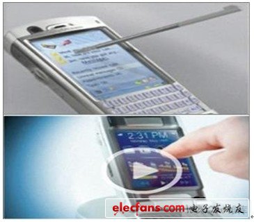
Figure 1: Finger and stylus detection capabilities make resistive touch screens easier to use
This article will mainly discuss the characteristics of resistive touch screen technology, the issues that should be paid attention to during the design process, and potential application areas.
Understand the design of electronic touch sensors and controller selection requirements
Because resistive touch screens are easy to buy now, and the price gradually decreases over time, the application of this technology is becoming wider and wider. In order to select the best touch screen technology, application designers must consider application requirements in depth. Resistive touch screen technology requires only a simple printed circuit board design. Unlike capacitive and inductive touch screen technology, electrodes or coils need to be etched on the printed circuit board. Because the touch screen directly covers the display screen, it can save the printed circuit board space required for mechanical switches or capacitive touch key electrodes. It is recommended not to use resistive touch screens in harsh environments, such as mines or construction sites where there are frequent explosions or excessive dust. Very little damage on the resistive touch screen will affect the touch accuracy and linearity.
Working principle of resistive touch screen
1. The resistive touch screen is a transparent glass plate covered with a touch response film.
2. The resistive touch screen panel consists of two resistive layers (indium tin oxide), with a thin separation layer in the middle.
3. The two thin film layers of the resistive touch screen form a resistor network, which acts as a voltage divider circuit for the touch position detection function.
4. The touch screen will cause a voltage change on the voltage divider composed of the resistance network. This voltage is used to determine the position of the touch point of the touch screen.
5. The touch screen controller (TSC) converts the captured analog voltage signal into a digital touch coordinate signal. The built-in analog-to-digital conversion channel acts as a voltmeter for measuring analog voltage.
6. After touching the screen, the touch controller acting as a voltmeter first applies a voltage gradient VDD at point X + and a ground voltage GND at point X-. Then, the analog voltage on the Y-axis resistance is detected, and the analog voltage is converted into a numerical value, and the X coordinate is calculated by an analog-to-digital converter (Figure 2). In this case, the Y-axis becomes the induction line. Similarly, by applying a voltage gradient at Y + and Y- points, the Y coordinate can be measured.
7. Some touch controllers also support touch pressure measurement, that is, Z-axis measurement. When measuring the Z-axis coordinates, the voltage gradient is applied to the Y + axis and X-axis.
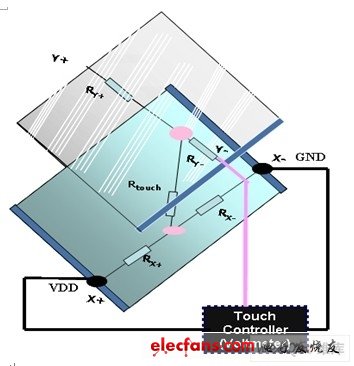
Figure 2: Resistive touch screen: X coordinate measurement:
There are two main forms of resistive touch: software touch solutions and dedicated touch screen controller chips.
In software tactile solutions, the microcontroller must be responsible for all touch detection and coordinate calculation tasks. The software algorithm based on the microcontroller adopts the internal microcontroller to measure the touch position voltage and execute the touch detection function and coordinate processing function.
In the dedicated touch screen controller, the controller initiates an interrupt request to detect a touch event to the system host (microcontroller) and outputs digital data representing touch coordinates. The main processor (MCU) then reads the digital data and executes the operation commands expected by the customer.
The design method based on MCU calculation parameters requires the main processor to be very fast, and only in this way can frequent touch operations be managed. For fast touch detection applications, this is not a very reliable design. Because there is no data averaging and touch detection delay function, the detection accuracy of this type of design is relatively low. The dedicated touch screen controller chip with data sampling, measured value averaging, touch detection delay configuration and digital touch coordinate calculation function is the real touch screen controller. These chips are easy to integrate into product designs and have higher performance.
Resistive touch screen classification
According to the number of sensing lines on the touch screen, the resistive touch screen can be further divided into three categories: 4-wire, 5-wire and 8-wire. The strip electrodes of the 4-wire touch screen are installed on two different resistance layers (X + and X- are on the same layer, and Y + and Y- are on the other resistance layer). The 5-wire touch screen only has round electrodes (X +, X-, Y + and Y-) on the bottom layer. The top layer is used to measure the voltage during touch, and the voltage gradient is only applied to the bottom layer.
The working principle of the 8-wire touch screen is similar to the 4-wire touch screen. Just add a reference voltage line to each line, so the final bus number reaches 8. The newly added 4 lines are used to provide reference voltage to the original 4 lines. The 8-wire touch screen adopts the measurement principle of proportional measurement analog-to-digital converter.
Because of the low cost and simple touch sensing algorithm, the 4-wire touch screen is widely used in low-end consumer electronics products. 5-wire and 8-wire touch screens are mainly used for expensive high-end medical equipment and important industrial controllers.
The main components of the touch screen solution include a touch screen panel, a touch screen controller (TSC), a display panel, and a main processor. As shown in FIG. 3, the main processor may be a low-end microcontroller. The main processor uses the one-wire or two-wire interface protocol (I2C / SPI) to manage the initialization of the touch screen controller and read digital coordinate data. The main processor is also responsible for converting the user's touch into required operations, such as volume adjustment, picture replacement or writing display. Most consumer electronics products have a display panel, and human-machine interaction icons can be displayed on the same display panel.
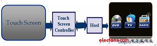
Figure 3: Structure diagram of the resistive tactile solution
To design an application system with a tactile user interface, the design complexity depends on the resolution requirements of the touch screen. The resolution of the touch screen also depends on the resolution of the analog-to-digital converter of the touch screen controller. Another important factor is the power consumption of the touch screen controller. It is recommended to choose a controller with an interrupt function and a low-power standby mode. When there is no touch operation, the controller enters a low-power standby state to save power; when a touch event is detected, the controller will wake up and perform the touch voltage decoding function. This feature becomes a basic requirement for portable devices, because every coulomb of power in a portable device's battery is very valuable.
Choosing a touch screen controller with a built-in cache is very beneficial for frequent touch detection applications. For example, writing is a continuous touch operation. If the touch screen controller includes a FIFO buffer, data processing can be performed after the FIFO buffer is full, which can reduce the processing overhead of the main processor. When the screen is large (> 6 inches), the noise picked up by the conductive board of the touch screen will affect the accuracy of the touch screen. Adding capacitors on the touch screen (in the X + / X-, Y + / Y-axis) can reduce high-frequency noise.
An example of a resistive touch screen
In order to understand the principle of the resistive tactile solution, we analyze a ready-made low-cost pen tablet solution (Figure 4). In this example, the resistance touch screen controller uses ST's advanced STMPE811 controller, and the main processor uses ST's STM32 high-density 32-bit microcontroller.
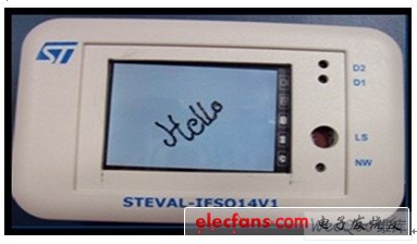
Figure 4: Tablet solution
This solution allows users to feel the beauty of real-time handwriting on the TFT-LCD panel. On a 4-wire resistive touch screen, the X and Y coordinates of the stylus are mapped to a line drawing in the TFT-LCD panel. In the existing handwriting board design, the 2.4-inch touch screen is installed on the 2.4-inch (QVGA resolution) TFT-LCD panel. Most mobile phones and PDAs use low-resolution displays. To ensure that touch detection coordinates are accurately mapped on the display screen, special attention should be paid to the resolution of the touch screen and the display panel. The change in touch coordinates along the resistive axis (X / Y) of the touch screen is another important consideration. This issue is related to the brand of the touch screen. On some touch screens, the coordinate values ​​obtained from the touch screen controller gradually decrease along the axis of the touch screen from top to bottom, and vice versa.
In this example, the touch screen controller is connected to a 32-bit microcontroller via an I2C protocol interface. The TFT-LCD panel is connected to the microcontroller through the flexible interface of the microcontroller (FSMC), and various parameters of the touch screen controller are configured through the microcontroller, such as the sampling speed and average value of the analog-to-digital converter. In addition to the I2C protocol interface, the touch screen controller provides an output interrupt pin, which is used to initiate a tactile detection interrupt request to the main processor. This interrupt pin is connected to the external interrupt port pin of the microcontroller. The touch screen controller used in this solution includes a 12-bit analog-to-digital converter and a FIFO buffer that can temporarily store 128 touch data sets. When the touch screen controller detects a touch event, the microcontroller will receive an interrupt request from the external interrupt port pin, and then read the data in the touch screen controller FIFO buffer through the I2C protocol. Each X-axis and Y-axis coordinate data uses a 12-bit value. The software mapping from the coordinates of the touch screen to the coordinates of the pixel display screen, the calculation base is the resolution of the display panel and the resolution of the touch screen. The microcontroller processes the coordinates of the TFT-LCD pixel display and then displays the corresponding TFT-LCD pixels. The resolution of the 12-bit analog-to-digital converter is sufficient. Therefore, very precise contact points can be obtained, which can make continuous pixels glow, providing users with a real-time line drawing feeling (Figure 5).
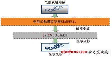
Figure 5: Handwriting tablet implementation process
Because the touch screen controller has a built-in FIFO buffer, it becomes easy to manage the processing overhead of the microcontroller. In addition, a color table can be displayed on the side of the display panel. The color of the text can be selected, as long as you click a color in the table, the next line drawing will become the selected color. The program also provides a clear button icon, when the screen is full of content, touch this button to clear the screen. In this way, designers can easily implement a brush function. This application may be the basis for children's drawing toolbox. (Menka Tangri, STMicroelectronics)
Mobile Phone Charging Usb Adapter Cable For iPhone
Five lengths
Each pause is a length, suitable for multiple occasions
Notice
Both cables are stretched at the same time
Do not stretch unilaterally
dual-use, small portable, easy to take durable
flexible length adjustment
4 In 1 Wireless Data Charging Cable
Guangzhou HangDeng Tech Co. Ltd , https://www.hangdengtech.com