Abstract: In order to solve the real-time communication problem of gyro combination data in a satellite information collection system, the design of the whole information acquisition system using CAN bus is proposed. Compared with the general information acquisition system, the lower computer of the system adopts the TMS320F2812 type DSP, and uses its eCAN module as the data transmission module. The upper computer adopts the industrial computer, and the ADLINK PCI/cPCI-7841 CAN bus interface card is used as the data receiving module. The received data is processed in real time by the industrial computer, and information collection and real-time monitoring are more reliably completed. The experimental results show that the system information collection is real-time, accurate and stable.
This article refers to the address: http://
CAN (Controller Area Network) is a controller area network, which is mainly used for fieldbus detection and control of various devices. In the early 1980s, the German company BOSCH developed a serial data communication protocol, the CAN bus, to solve the data exchange between many control and test instruments in modern automobiles.
CAN bus is a serial communication network that effectively supports distributed control or real-time control. It provides powerful technical support for distributed control system to realize real-time and reliable data communication between nodes. CAN belongs to the field of industrial fieldbus. Compared with the general communication bus, CAN bus data communication has outstanding reliability, real-time and flexibility, and the communication speed can reach 1 Mb/s.
At present, CAN bus is not only used in the automotive field, but also in the fields of automatic control, aerospace, machinery industry, agricultural machinery, robotics, CNC machine tools, medical equipment and sensors.
As CAN is adopted and promoted in more and more different fields, it has led to the standardization of communication messages for various application fields. To this end, in September 1991 PHILIPSSEMICONDUCTORS developed and published the CAN Technical Specification (VERSION 2.0). This technical specification includes parts A and B. 2.0A gives the CAN message format defined in CAN Technical Specification 1.2, which provides an 11-bit address; and 2.0B gives the standard and extended 2 message formats, providing a 29-bit address. Since then, in November 1993, ISO officially promulgated the road traffic vehicle—digital information exchange—the high-speed communication controller local network (CAN) international standard (ISO11898), which paved the way for standardization and standardization of controller local network. the way.
According to the communication requirements of the navigation data of a certain type of satellite information acquisition system, and to ensure the real-time reliability of information collection, the CAN bus is used to complete the design of the whole information acquisition system.
1 Information acquisition system design:
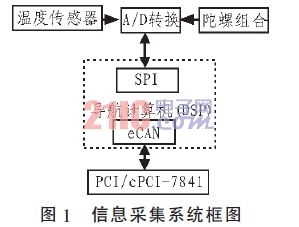
Due to the complicated operating environment of the satellite, the collected gyro combination data will have corresponding errors. Therefore, it is necessary to perform telemetry on the collection of navigation data to monitor the bus state of the navigation computer. The system uses the CAN bus to complete the entire information collection and real-time monitoring according to the communication needs of a certain type of satellite. A block diagram of the information acquisition system is shown in Figure 1.
1.1 System hardware design:
Because TI's TMS320F2812 DSP has been applied in the military, and based on various performance comparisons, the system uses TMS320F2812 DSP as the navigation computer to transmit the data of the lower computer. The eCAN module is the enhanced CAN on the TMS320F2812 DSP. The performance of the controller is greatly improved compared with the existing DSP built-in CAN controller. The data transmission is more flexible and convenient, the data volume is larger, the reliability is higher, and the function is more complete.
The upper computer adopts the industrial computer, in which the data is received by the ADLINK PCI/cPCI-7841CAN bus interface card. The card can operate two independent CAN networks at the same time, programmable transfer rate up to 1 Mb/s, fast access to CAN controller through direct memory mapping, PCI bus plug and play, bus controller SJA1000, electrical interface For 82C250.
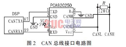
The information communication system information communication is completed by CAN bus. The CAN bus interface circuit is shown in Figure 2. The unique feature is that a terminal resistor R is 120 Ω connected in parallel between the output pins CANH and CANL of the transceiver PCA82C250. The effect of impedance mismatch at the far and near ends.
As shown in Figure 1, the eCAN module of the TMS320F2812 DSP transmits the gyro combination data and temperature values, and the PCI/cPCI-7841 CAN bus interface card of the host computer receives data, thereby completing the entire information collection and monitoring process.
1.2 System software design:
The system software mainly completes the data communication based on the CAN bus, and after receiving the data, processes the collected navigation data as required, converts it into the actual required data type, and monitors the state of the gyro combination.
The CAN bus communication message format of this system adopts the CAN2.0B extended mode. The communication data format is mainly defined in the CAN bus protocol (ArbitrationField) and (Data Field), which requires a data transmission rate of 500 Kb/s. . The protocol frame format is shown in Figure 3.

The system's receiving software design flow chart is shown in Figure 4.
Before using the CAN interface card, first initialize the parameters such as baud rate and transmission message format.
1) The transmission message format of the initialization CAN bus is CAN2.0B extended mode providing 29-bit address; 2) The baud rate of initializing the CAN bus is 500 Kb/s.
Use the CanOpen-Driver () function of the PCI/cPCI -7841CAN interface card to open the CAN port, initialize it with the CanConfigPort() function, send the packet with the CanSendMsg() function, and receive the packet with the Can-RcvMsg() function, using CanCloseDriver ( The function closes port [3]. Create a receiving thread that processes the data as needed after receiving the data. Use MFC to create a communication interface. Note that a thread function can only be a static member function, or a function declared outside the class.
The initialization procedure is as follows:
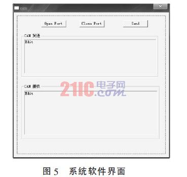
PORT_STRUCT setPort;long handle[2];HANDLE rcvEvent0;HANDLE rcvEvent1;setPort.mode = 1; // 0 : 11-bit ; 1 : 29-bit CAN networksetPort.accCode = 0; // Only ID = accCode can pass thefiltersetPort .accMask = 0x7FF; // Don't care bitsetPort.baudrate = 2; // 0:125 Kb/s; 1:250 Kb/s; 2:500 Kb/s; 3:1 Mb/s//open porthandle [0] = CanOpenDriver(0, 0);handle[1] = CanOpenDriver(0, 1);CanConfigPort(handle[0], &setPort);CanConfigPort(handle[1], &setPort);//get the receive event handleCanGetReceiveEvent (handle[0], &rcvEvent0); CanGetReceiveEvent(handle[1], &rcvEvent1); The system software interface is shown in Figure 5.
2 Experimental results:
After experimental verification, the data collected by the information acquisition system is unchanged after communication, ensuring reliable and accurate information collection.
3 Conclusion:
Because the data communication based on CAN bus has outstanding reliability, real-time and flexibility, and because the eCAN module of TMS320F2812 DSP makes data transmission more flexible and convenient, the data volume is larger, the reliability is higher, and the function is more complete. The data transmission of the lower computer is carried out, and the PCI/cPCI CAN interface card performs data reception, thereby completing information collection, and correspondingly processing the collected data to monitor the state of the gyro combination, which is of great significance for navigation of satellites and the like.
Solar speaker is a new generation of speaker based on solar energy, which is stored as electricity through high-quality solar cell photovoltaic chip conversion technology, and uses the latest wireless transmission technology such as Bluetooth, Wifi, Airplay and other wireless remote control music playback products using mobile phones or other computers, television and other 3C devices. The birth of this new concept speaker subverts the traditional impression that the wiring, wiring and routing of speakers are troublesome and cumbersome. It completely gets rid of the dependence of speakers on wiring and power. It realizes the demand of music playing anytime and anywhere in indoor and outdoor environment and enjoys music anytime and anywhere. The wireless function is integrated into the solar stereo so that speakers can be used everywhere. All-weather wireless speakers can be connected to any audio device without damage to the sound quality, and wireless signals can pass through walls, floors or even the ceiling. Because speakers are placed outside, they can ensure sufficient electricity. Fizz Global customizes solar audio series:Bluetooth Speaker Flashlight. Waterproof Intelligent Loudspeaker Box,etc.,let the world ,where the sunshine , where the music is.
Solar Speaker System,Wireless Speaker System,Solar Power Speaker System,Portable Solar Speaker System
ZHEJIANG FIZZ NEW ENERGY CO.,LTD , http://www.ywfizz.com