Central issue:
This article refers to the address: http://
Power consumption of automotive internal electronic systems
solution:
Improve the conversion efficiency of components
Use a switching switching regulator instead of a linear regulator
High performance analog DC-DC converter
Now, automakers are continually integrating increasingly complex electronic systems into their cars. Allied Business Intelligence predicts that annual sales in the automotive semiconductor market will rise from $12.3 billion last year to $17 billion in 2007. The strategy analyst of another company also put forward the same point: for an ordinary car, the cost of the electronic system will account for more than 20% of the entire car, but by 2008, this proportion will increase to 30%. . Typical in-vehicle electronic systems include: anti-collision radar, adaptive cruise control, tire pressure monitoring, navigation systems, hands-free cellular telephones and other wireless connections, and access using biometric parameters.
A significant increase is reflected in the DVD/HDD navigation system. The first DVD/HDD navigation system was introduced in 1997, and this year's worldwide sales of such systems are expected to exceed 13 million units. For any type of electronic product, the car's environment is still very demanding. The large operating voltage range required, coupled with the high transient voltages and large temperature variations, put together these challenges and pose a huge challenge to electronic systems. In addition, the performance requirements of electronic systems are becoming higher and higher, and it is also necessary to be able to provide different voltages for different components within the system.
Most of the high-end cars currently produced in the car use the DVD global positioning navigation system as a standard equipment in the car. However, designing a power supply that satisfies all of the different voltage requirements in such a system is as complex as designing a laptop's power supply. A typical navigation system requires at least six voltages: 8V, 5V, 3.3V, 2.5V, 1.5V, and 1.2V. The 8V voltage is used to power the DVD motor. It is used to drive the rotation of the disc. Under normal circumstances, it requires a peak current of up to 2A. The 5V and 3.3V voltages are typically supplied to the system bus, and both require 2A to 3A of current. The 1.5V and 1.2V voltages are the supply voltages of the CPU core and the DSP core, respectively. The power of these two voltages is generally between 3W and 5W.
At the same time, the number of components is constantly increasing, and the available space is getting smaller and smaller. Since the actual heat required to dissipate is too large, it is difficult to dissipate the heat. Because space is limited and the operating temperature is required to be within a certain range, conversion efficiency becomes more and more important. When the output voltage is low and the current is moderate (about a few hundred milliamps or more), it is not possible to simply use a linear regulator to generate the voltages required by these systems. Thus, in the past few years, mainly due to thermal limitations, switching regulators are gradually replacing linear regulators. The benefits of switching regulators are: higher efficiency and smaller size, which outweighs its complexity and electromagnetic interference.
For switching regulators that are planned for use in car navigation systems, due to these limitations, it must have the following features and features:
â—The input working voltage range is wide;
â— High efficiency over a wide range of loads;
â—In normal working mode, standby mode and shutdown mode, the quiescent current must be very low;
â—The thermal resistance is small;
â— Noise and electromagnetic interference are very small.
The input voltage has a wide operating range. The switching voltage range of any switching regulator must be between 3V and 60V, in order to meet the "cold start" and "large load" requirements. It also has the added benefit that the automotive system can operate at either 14V or 42V. In addition, another benefit of using a 60V rated voltage is that it leaves room for the 14V system to control the voltage from 36V to 40V. Furthermore, with this 60V rated voltage, this device can be used in the new 42V system in the future. In other words, the design of a 14V system can be easily upgraded to a 42V system without having to re-do many designs.
effectiveness. For most automotive systems, it is important to maintain high power conversion efficiency over a wide range of loads. For example, for applications with an output voltage of 5V and a load between 10mA and 2.5A, the power conversion efficiency is expected to be 85%. When the current is large, the internal switch must be fully saturated. In general, the power consumption is 0.1W at a current of 3A. In order to improve light load efficiency, the drive current can be reduced or the drive current can be proportional to the load current. In addition, the internal control circuitry can be powered by an offset pin that can be powered by the output voltage. This takes advantage of the high power conversion efficiency of the buck converter. The bias current is derived from the output rather than from the input, so the current drawn by the control circuit from the power supply is reduced. The multiple of the reduction is the ratio of the input voltage to the output voltage. Requirements for the input current source. For example, when the output voltage is 3.3V and the output current is 100 basis, the average input current required from the 12V voltage is 30 basis. This reduces the current required by the control circuit, thereby increasing efficiency at light loads.
The quiescent current is small. Many products in automotive systems require continuous supply of electricity even when the car is stationary. An important indicator for these products is the small quiescent current. If the output current is not less than 100mA, then the device will always operate in normal switching mode. When the current is below 100mA, the switching regulator must skip some pulses to maintain regulation. The regulator can enter deep sleep mode between the two pulses, in which only a portion of the internal circuitry is powered. When the load current is small, the switching regulator should automatically switch to burst mode. In this mode, the quiescent current of the 12V to 3.3V converter will drop below 100. In sleep mode, the internal reference voltage and power good indicating circuitry are still operating to monitor the output voltage. In the off state, the quiescent current should be lower than 1 base.
The thermal resistance is small. Under ideal conditions, the thermal resistance of the semiconductor junction to the outer casing should be small. If the copper on the back side of the device is bare and soldered to the surface of the Printed Circuit Board, the heat from the device can be dissipated through the printed Circuit Board. The four-layer circuit board that is often used today has a power layer in the middle, and its thermal resistance is in the range of 40 ° C / W. For products used in environments with high ambient temperatures, their heat transfer to the metal case is very good. The thermal resistance is close to the thermal resistance of the semiconductor junction to the case, usually 10 °C / W, thus expanding the effective operating temperature. range.
Noise and electromagnetic interference problems
Switching regulators generate more noise than linear regulators, but they are much more efficient. In many products susceptible to noise, as long as the performance of the switching power supply is known in advance, the magnitude of noise and electromagnetic interference can be controlled. If the switching regulator is fixed in normal mode, the rising and falling edges are also clean and predictable during turn-on and turn-off, and there is no overshoot or high-frequency fading oscillations, thus reducing electromagnetic interference. Its small package size and high operating frequency make it possible to arrange the circuit very compact and small, thus reducing electromagnetic interference radiation. In addition, if this regulator can use a ceramic capacitor with a small equivalent series resistance, it can reduce the input voltage ripple and output voltage ripple, which is another noise source in the system.
Obviously, designing and developing such switching regulators is not a simple matter. However, the latest example of a high voltage DC-DC converter is a step-down switching regulator monolithic integrated circuit with a voltage of up to 60V. It has an input voltage range of 3.3V to 60V (Figure 1) and is very efficient when the load current is as high as 2.5A. The reference voltage has an accuracy of ±2% at all input voltage, load and temperature conditions.
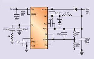
In burst mode, its quiescent current is less than 100, suitable for products with input voltages from 12V to 3.3V. This device is available in a thin TSSOP package with very low thermal resistance for small designs. Finally, it uses a current-mode circuit that has good transient response, is easily compensated, and uses a proprietary circuit that keeps the peak current in the switch constant at any duty cycle. Its switching frequency is fixed at 200kHz, and in addition, this product can be synchronized with higher frequencies. It has excellent regulation over the entire automotive temperature range and provides power good signal/reset, soft start and UVLO functions. This circuit is a reliable, high efficiency step-down converter solution with currents up to 2.5A and small size for automotive use.
Although the design of car navigation systems is very complex and requires high performance analog DC-DC converters, there is no need to worry about it. Vendors are introducing a wave of "new wave" regulators that combine a number of essential features to free system engineers from the arduous power supply design effort.
With the progress of science and technology, human beings are exploring step by step. As the carrier of Electronic Products, the technology of PCB Board is also more and more high-end. The design of PCB is more and more precise. Therefore, our production and processing also need improvement.
Now many research institutes in China have cooperated with us to discuss the contribution of PCB to the development of science and technology and to the human society.

Scientific Research PCB Board,Circuit Board Recycling,PCB Recycling,Printed Circuit Board Recycling
Orilind Limited Company , https://www.orilind.com