Since the car sensor can measure and control various information such as temperature, pressure, position, speed, acceleration and vibration in real time and accurately, as the information source of the electronic control system of the car, the car sensor is not only a key component of the electronic control system of the car. It is also one of the core contents of research in the field of automotive electronics technology (the principle of automotive sensors). So, how to realize the design of automotive sensors? Xiaobian introduced the knowledge of automotive sensor interface and hardware design (the application of automotive sensors) by collecting and sorting data.
This article refers to the address: http://
Before we understand this knowledge, let's take a look at the relevant knowledge about ESP, which is closely related to automotive sensor design.
Introduction to ESP basics
What is ESP? Simply put, ESP (Electronic Stability Program) is a landmark invention of automotive electronic control. Different R&D institutions have different names for this system, such as Bosch (Cars), which was called Automotive Dynamics Control (VDC) in the early days. Now Bosch and Mercedes-Benz are called ESPs; Toyota is called Car Stabilization. Sex Control System (VSC), Automotive Stability Assist (VSA) or Automotive Electronic Stability Control (ESC); BMW is known as Dynamic Stability Control (DSC).
Although the names are not the same, they are based on traditional vehicle dynamics control systems, such as ABS and TCS, which add a lateral stability controller to control the distribution and amplitude of lateral and longitudinal forces in order to control the car in any road condition. Dynamic motion mode, which can improve the dynamic performance of the car under various working conditions, such as braking, slipping, driving and so on. ESP has been mass-produced abroad, and it is still in the research stage in China. To achieve the degree of industrialization, there is still a lot of work to be done. Figure 1 shows the structure of an automotive ESP.
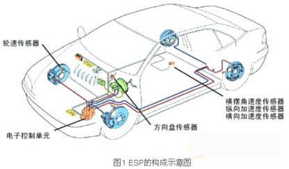
The electronic components mainly include an electronic control unit (ECU), a steering wheel sensor, a longitudinal acceleration sensor, a lateral acceleration sensor, a yaw rate sensor, a wheel speed sensor, and the like. ESP is an important electronic control system for ensuring driving safety. The normal operation of each sensor is the basis for effective control.
Let's take a look at the hardware interface design of ESP commonly used sensors.
ESP common sensor interface design
ESP common sensor interface design block diagram shown in Figure 2.
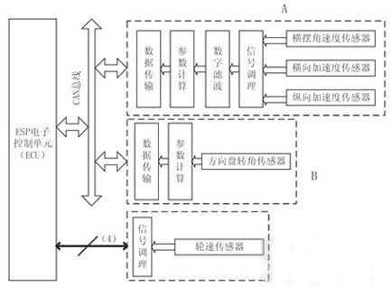
ESP common sensor interface design block diagram
In the figure, the steering wheel angle sensor signal is processed by the microcontroller and sent to the ECU through the CAN bus (B in Fig. 2); the yaw rate sensor and the longitudinal/lateral sensor are designed in the same way because of the similar signal characteristics and installation position. In the module (A in Figure 2); because ESP has high requirements on the real-time performance of the wheel speed sensor signal, it is directly sent to the ECU (C in Figure 2) after signal conditioning.
In A and B of Figure 2, the microprocessor is required to process the signal and transmit data through the CAN bus. This article uses Infineon's SAK-C164CI. Designed for automotive applications, the chip features an AD converter, input signal capture, and quadrature decoder for fast operation and is ideal for ESP sensor signal processing.
Automotive wheel speed sensor hardware design
The block diagram of the hardware structure of the wheel speed sensor based on the 80C31 MCU (external expansion 8kRAM and 8kEPROM) is shown in Figure 3. The peripheral circuit has signal processing circuit, bus control and bus interface.
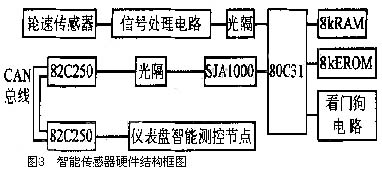
After the wheel speed sensor generates a signal, it is filtered, shaped, and optically isolated, and sent to the /INT0 input pin of the 80C31. T1 is used as a timer to periodically measure the pulse signal. SJA1000, 82C250 form the control and interface circuit with CAN bus. In the design process of the wheel speed sensor, full consideration is given to its anti-jamming and stability. The input/output terminals of the MCU are optically isolated, and the watchdog timer (MAX813) is used for time-out reset to ensure reliable operation of the system.
Signal processing circuit
According to the signal characteristics of the wheel speed sensor, the processing circuit is composed of a limiter circuit, a filter circuit and a comparison shaping circuit, as shown in FIG.
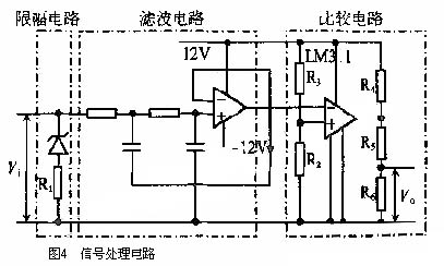
The limiter circuit limits the amplitude of the positive half cycle of the wheel speed sensor output signal Vi to 5V or less, and the output of the negative half cycle to -0.6V. The filter circuit is designed as an active low-pass filter with feedback. The cut-off frequency is 2075Hz (designed at the maximum speed of 200km/h, the frequency corresponding to the sensor output signal), and Q=0.707 is selected.
A certain comparison voltage is set in the comparison shaping circuit, and the square wave signal is output compared with the filter output signal. The amplitude of the LM311N output square wave is 10V. After R5 and R6 are divided, the square wave signal with the amplitude of 5V is sent to the optical isolator.
to sum up
In recent years, microelectromechanical systems (MEMS) technology developed from semiconductor integrated circuit technology has matured, and it can be used to make various kinds of sensitive and detecting mechanical quantities, magnetic quantities, thermal quantities, chemical quantities and biomass. Miniature sensors, which are small in size and energy consumption, enable many new functions, are easy to produce in high volume and high precision, and are low in cost per unit. They are easy to form large-scale and multi-function arrays, making them ideal for automotive applications.
After understanding the ESP: electronic stability program, this paper makes a simple analysis of the automotive sensor interface design, automotive wheel speed sensor hardware design and signal processing circuit.
Deluxe Rice Cooker was one of electric type rice cooker , but it`s the most popular type of electric rice cooker . especially famous in Southeast Asia area with its good appearances with various functions. Not only its outer shell could be customized with different demands, but also it speeding cooking , saving times and electricity, enhancing our lifestyle
Features
The inner pot is made of solid and durable aluminum alloy of high intensity , such as non-stick inner pot , stainless steel inner pot and honeycomb patterned inner pot with non-stick coating.
There are some models that use stainless steel instead of aluminium .Various other materials, such as copper, pure carbon, ceramic, and diamond powder coating, may be used for higher heat conductivity or better taste.
Applications
Multifunction , can cooking rice, soup and much more. added cooking versatility with supplied steam tray.
Some rice cookers have settings for congee, a type of rice porridge called okayu in Japanese, Juk in Korea, and zhou in Chinese.
More elaborate recipes are possible using a rice cooker, and there are cookbooks devoted entirely to dishes prepared using a rice cooker. It is possible to cook soups, stews or sponge cakes in electric rice cookers. By simply adding ingredients and setting it to "warm", a rice cooker cooks the contents at about 65 °C (150 °F). In a few hours, the stew is fully cooked and ready to eat.
Deluxe Rice Cooker
Deluxe Rice Cooker,Cylinder Rice Cooker,Mini Rice Cooker,Stainless Steel Rice Cooker
Guangzhou Taipeng Electrical Appliances Technology CO., LTD. , https://www.kettles.pl