Introduction to the highway non-stop charging system (ETC)
This article refers to the address: http://
The non-stop charging system (also known as the electronic toll collection system Electronic Toll Collection System, referred to as ETC system) is an intelligent transportation subsystem that uses RFID technology to realize automatic charging of vehicles without stopping. The system uses the short-range communication of OBU (OnBoard Unit) between the roadside unit RSU (RoadSideUnit) and the in-vehicle electronic tag to automatically complete the charging process without driver parking and charging personnel operation.
Introduction to MSP430
TI's MSP430 microcontroller product family features a 16-bit RSIC architecture for ultra-low power consumption. As the latest product sequence of MSP430, F5xxx adopts 0.18um process for the first time. The current consumed by 1MIPs is as low as 160uA, and the main frequency reaches 25MIPs. At the same time, MSP430F5xxx provides a wealth of on-chip functional modules, such as hardware RTC, 12-bit ADC, flexible clock system, hardware CRC16, power management module and multi-channel flexible and powerful DMA, support data exchange in standby mode.
ETC vehicle unit structure
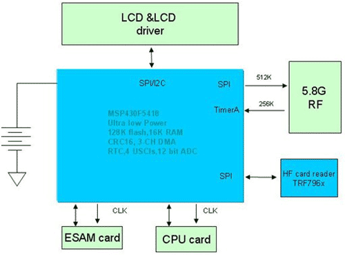
Figure 1.ETCOBU structure diagram
As shown in Figure 1, the OBU consists of a battery system, MCU, radio frequency, display and card reading parts (ESAM card, CPU card, RF card). As the center of the whole system, the MCU manages the display, card reading and data processing and exchange with the RF part.
Please refer to Figure 2 for the data format.
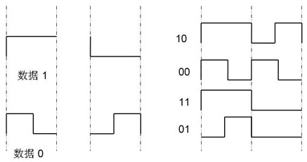
Figure 2. FM0 encoding
FM0 coding method introduction
When the vehicle passes through the toll booth, the OBU and RSU perform high-speed data exchange through 5.8G carrier modulation. The data is modulated with HDLCFM0. The FM0 code follows the following three rules:
A. There is a level jump in one cycle to indicate "0";
B. No level jump in one cycle means "1";
C. The two adjacent periods are opposite in level.
On-board electronic tag (OBU) challenges to MCU
The in-vehicle electronic tag system has two challenges for the MCU. One is low power consumption; the other is high-speed data communication capability.
The battery of the on-board electronic tag requires a life of more than 5 years or can support more than 10,000 transactions. The low-power design of the entire system is a top priority for engineers. Secondly, the RSU has a baud rate of 256Kbps for the OBU downlink data and 512Kbps for the upstream data. Since the vehicle transit time is very short, the OBU needs to respond quickly to the RSU's data and commands. The maximum length of the data packet can reach 1Kbits, and the OBU is not allowed to decode after receiving the entire data packet. This requires the MCU to have real-time codec capability.
In general, soft decoding of FM0 requires the level width of the data to achieve decoding. There are usually two ways. One is that Timer captures the data edge, and then the software determines the width between the data edges in the interrupt. The other is to periodically sample the level of the data port line and obtain the level width by counting. The ETC downlink data rate reaches 256Kbps. For data "0", the width between data transition edges is only 2uS. For data "1", the data edge width is only 4uS. Taking the first method as an example, the traditional soft decoding method is as follows:

Figure 3. Timer capture interrupt mode
As shown in Figure 2, during data reception, Timer captures a data edge every 2uS or 4uS and saves the data edge to the corresponding register. Therefore, the data in the Timer capture register will be updated every 2uS at the earliest. This requires the CPU to be fast enough to complete the decoding process within at least 2uS. Otherwise, the data in the Timer capture register will be overwritten by the new data, causing a decoding error. Assuming that the time required for the MCU to complete 1 bit decoding requires 50 cycles, then at least the MCU main frequency needs to reach 25 MIPS or more to achieve real-time decoding. Usually, we will choose MCUs with a frequency of more than 40MIPs, and these high-speed MCUs often have difficulty in meeting the requirements of ETC systems. Therefore, many ETC manufacturers use dual MCUs to implement FM0 real-time codec by a high-speed MCU. There is also a low-power MCU, usually MSP430, to manage the power consumption of the entire system. This adds to the cost and complexity of the system. With the advent of MSP430F5xxx, it can meet all the challenges of the ETC system to the MCU and solve the customer's troubles.
Method for realizing FM0 real-time decoding by using F5xxx on-chip DMA and TimerA capture function
The MSP430F5xxx's superior low power consumption meets the low power requirements of the ETCOBU. As the latest product sequence of MSP430, F5xxx adopts 0.18um process for the first time. The current consumption of 1MIPs is as low as 160uA. The on-chip PMM (Power Management Module) allows users to flexibly adjust the core voltage according to MCU load to ensure the lowest power consumption. In addition, it has a variety of low power consumption states. In the typical LPM3 mode, the RTC is turned on and the power consumption is only 2uA with the RAM data held.
In addition to excellent low-power characteristics, the MSP430F5xx main frequency can only reach 25MIPS, but because of the flexible multi-channel DMA, it can be linked with the Timer to realize automatic data movement without disturbing the CPU, which greatly enhances. The MCU's data throughput capability makes the main frequency no longer a bottleneck, and completes near-real-time decoding of FM0. In addition, the hardware CRC16 module allows the MCU to perform data verification only by manipulating registers. The real-time decoding process using DMA and CRC16 is shown in Figure 4:

Figure 4. Decoding of DMA automatic data movement
During data reception, the Timer captures a data edge every 2uS or 4uS. At this time, the DMA is automatically triggered. The DMA automatically moves the data of the Timer register to the specified array in the RAM area. The entire data reception process does not require the participation of the CPU. With the existence of DMA, the CPU does not need to frequently enter and exit interrupts to fetch data, and there is no need to worry about the loss of Timer capture register data, just focus on the decoding process.
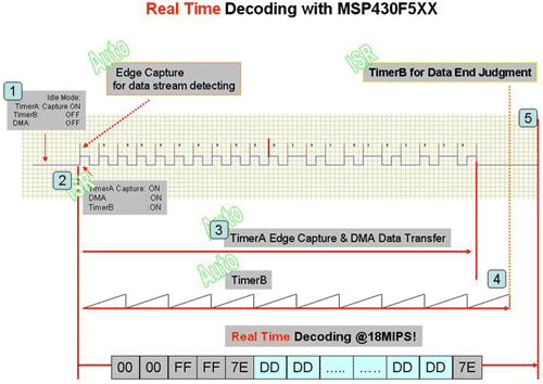
Figure 5. FM0DMA mode decoding icon
Description of the decoding process:
1. Standby state: TimerA is configured in capture mode, enabling TimerA interrupt, waiting for data to arrive
2. Capture the first data edge: Enable DMA in TimerA interrupt, enable TimerB and TimerB interrupt
3. Data reception: DMA automatically moves subsequent data edges to the memory array; at the same time, MCU decodes
4. End of data: TimerB judges the end of data reception
5. End of decoding

Figure 6. Program flow chart
results of testing:
The FM0 decoding test is performed using 120 bytes of data, wherein the data bits "1" and "0" each account for about 50%. After the MSP430F5438 completes decoding, the data is output through the serial port as shown in Figure 7:
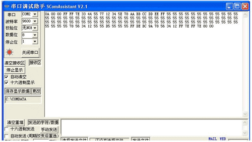
Figure 7. Data received by the serial port
For the 1Kbits data in the above figure, the measured MCU completes the decoding, and the lag packet reception is about 220uS. As shown in Figure 8.
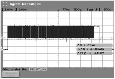
Figure 8. Decoding real-time
FM0 encoding and sending method using MSP430F5xxSPI and DMA
The uplink data rate of the ETCOBU system MCU is 512Kbps. FM0 data transmission can be easily completed by flexible application of on-chip DMA and SPI modules

LC Patch Cord is a fiber optic cable used to attach one device to another for signal routing. LC stands for Lucent Connector. It is a small form-factor fiber optic connector, half the size of the SC. LC Fiber Patch Cord divides to Single Mode and Multi Mode Fiber Optic Patch Cord. According to the connector structure type, it divides FC, SC, ST, MU, D4, E2000, LC etc.. According to the polished ceramic end-face, it divides to PC, UPC and APC.Fiber Patch Cord such as Riser Jacket (OFNR), Plenum Jacket (OFNP), PVC Jacket, Low Smoke Zero Halogens (LSZH).The LC Fiber Patch Cable is available in both single mode and multimode versions, and is fully intermateable with fiber optic products. LC LC patch cord both single mode and multimode versions LC fiber patch come with a zirconia ceramic ferrule with pre-polished UPC profile and convex spherical end. These end face types allow for faster polishing, and low back reflection and optical loss, while ensuring maximum repeatability.
LC Patch Cord
LC Patch Cord,LC Fiber Patch Cord,Fiber Patch Cord LC,LC Fiber Patch Cable
Foclink Co., Ltd , http://www.scfiberpigtail.com