With the continuous development of science and technology, the number and application of electronic devices are gradually increasing, and as a result, electromagnetic interference will become more and more serious.
This article refers to the address: http://
In the increasingly harsh electromagnetic environment, if proper electromagnetic shielding measures are not taken, electromagnetic interference between devices will become increasingly serious, and the performance of electronic devices will decline, which may endanger the security of information. In order to ensure that the electronic equipment does not interfere with other equipment in the complex electromagnetic environment, and is not affected by the interference of other equipment, it can work normally. This requires strict electromagnetic construction from the aspects of structure and technology in the initial stage of equipment development. Compatible design.
1 Basic requirements for electromagnetic compatibility design
Electromagnetic compatibility is one of the main performances of electronic devices. Electromagnetic compatibility design should also be carried out while designing device functions.
The purpose of electromagnetic compatibility design is to make the designed equipment electromagnetic compatibility in complex electromagnetic environment. Therefore, the following requirements should be met when designing electromagnetic compatibility: Firstly, the electromagnetic compatibility index satisfied by the equipment is clarified, and then the sensitive device and interference of the equipment are determined. Source and interference channels, targeted measures, and finally through the test to understand whether the equipment meets the requirements of electromagnetic compatibility indicators.
2 Electromagnetic compatibility design method
For a communication vehicle, it usually has a large amount of equipment, including power distribution equipment, communication equipment, and terminal equipment. Electromagnetic interference is easily formed between the equipments, which affects the communication quality. Therefore, the equipment must be designed for electromagnetic compatibility. Starting from the 3 elements (interference source, coupling path and sensitive equipment), various effective means are adopted to suppress the interference source, eliminate or weaken the interference coupling, and increase the anti-interference ability of sensitive equipment.
Taking an in-vehicle electronic device as an example, it consists of a digital ammeter, a digital voltmeter, a transfer switch, a circuit breaker, a control protection unit, a transformer, a contactor, and the like, and a digital ammeter, a digital voltmeter, a changeover switch, and an open circuit. The device is arranged on the front panel, and the control unit, the transformer, the contactor and other components and components are placed inside the chassis. This equipment should meet the requirements of electromagnetic compatibility indicators related to GJB151A-97. The main measures taken in structural design are: shielding of instrument window; shielding of chassis gap; rational layout and shielding of each unit; cable laying and power line filtering, etc. .
2.1 Screening of the instrument window
The instrument window is a relatively large leakage port for the equipment, and effective measures must be taken to shield it. For this reason, the digital ammeter and the digital voltmeter are externally shielded by adding a screen shielding glass. Screen shielding glass is made by a low-impact wire mesh sandwiched between two layers of glass by a special process. The density of the screen mesh determines its main shielding effectiveness. As shown in Figure 1, due to the 10~20 mm wire mesh burr around the glass, it is pressed against the chassis by screwing the metal frame to obtain a continuous conductive surface to reduce electromagnetic leakage. .
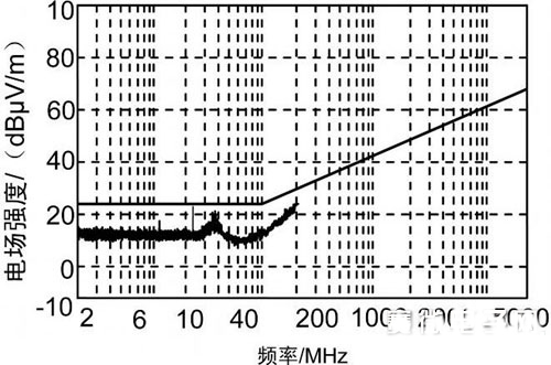
Figure 1 Screening of the meter window
2.2 Shielding of the chassis gap
The main factor affecting the integrity of the shield is the seam on the shield. The frame of the in-vehicle electronic device is made by bending and then welding the aluminum plate. The weld seam is smooth and continuous, and it is a permanent joint. The RF resistance of the joint is almost the same as the RF resistance of the metal plate itself, thus ensuring shielding. Electrical continuity at the body joint. For detachable joints, such as chassis and cover joints, screw fastening is often used. Because the spacing of the screws should not be too small, the unevenness of the joint surface and the warpage of the cover material, etc., the joint surface Inevitably, gaps are created, which reduces the shielding effectiveness of the chassis. Two methods have been taken to solve this problem: Increase the gap depth. In order to increase the gap depth, the flange width of the chassis is 15 mm. The larger the overlap size, the shielding. The better the performance; the smaller the gap length, because the sheet metal chassis is difficult to achieve high precision at the joint surface, in order to make up for this defect, an economical and practical method is adopted, and a beryllium bronze reed with adhesive backing is applied at the joint surface. Since the reed has a certain elasticity, the reed is deformed after assembly, and the contact surface generates a certain pressure, so that the joint has a certain electrical continuity.
2.3 The layout of each unit inside the chassis and its shielding
Reasonably arranging the positions of the various units and components in the equipment can reduce the degree of interference economically and practically. First of all, the source of interference and the sensor must be clarified. In this device, the source of interference is the control protector. The sensitive device is a digital ammeter and a voltmeter. To avoid the proximity of the two, place them in the rear and front of the chassis. The spatial distance reduces the electromagnetic interference of each other. In order to achieve a more effective shielding effect, a shield box is placed on the periphery of the body of the current and voltmeter, the head of the meter is closely attached to the shielding glass of the front panel, and the wire mesh burr of the glass is shielded by the metal frame and the chassis and the shield are shielded. The boxes are integrated so that the body is completely in the electrical continuous metal cover (as shown in Figure 1), and the current and voltmeter leads are introduced by the feedthrough capacitors mounted on the shield, so that the leads are sensed. The interference signal is bypassed to ground. The same control protector is also shielded by a shielding box, which further reduces its external radiant energy, thereby obtaining a better shielding effect.
2.4 Cable selection and laying
Because the cable is an efficient electromagnetic wave receiving and radiating antenna, it is also a good channel for interference conduction. The electromagnetic compatibility problem of most equipment is caused by cable. One of the main methods to solve the cable problem is to shield the cable, so this equipment is selected. The shield has good quality (low impedance) cable, and the cable shield is shielded from the low impedance of the chassis 360. The shield and the chassis form a complete shield, which can solve the problem of cable radiation to a certain extent. At the same time, in the electrical wiring, the power distribution line is required to maintain a distance of 150mm from other types of lines. The sensitive circuit and the interference circuit are separately laid, cannot overlap, and the spacing of the wiring harness is increased to avoid the coupling between the cables. .
2.5 Power Line Filtering
In order to suppress the influence of the high-frequency interference signal at the power input terminal on the system, an EMC power line filter is added. The filter is different from other electronic components, and its performance has a lot to do with its installation method, so a series of measures have been taken in the way the filter is installed. As shown in Figure 2, first, the filter input and output lines should be far away to avoid the phenomenon that the high-frequency filtering effect is deteriorated due to the coupling between the two ends. Secondly, the filter case is in low-impedance contact with the chassis, and the power port is shortened. To the connection of the filter, when the current enters the chassis, it flows through the filter for filtering, and then to other units; finally, the connection between the power port and the filter is also shielded, so that external electromagnetic interference cannot be along When the power cable enters the device, the electromagnetic interference inside the chassis cannot be transmitted out of the chassis, causing the interference to exceed the standard.
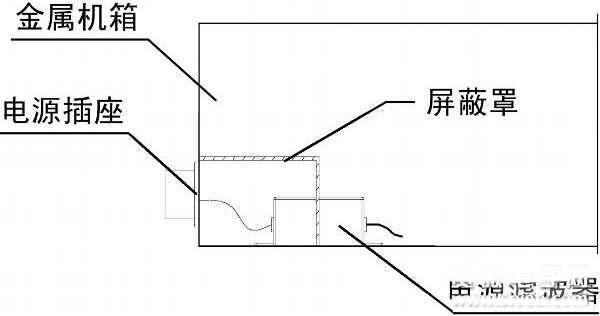
Figure 2 Power filter installation method
2.6 Grounding
Grounding is a very important problem in electronic equipment. It can make there is no potential difference between the grounds of all the unit circuits in the whole circuit system, ensuring that the equipment can work stably.
A grounding post, that is, a chassis ground, is mounted on the rear panel of the in-vehicle device. The casing ground can discharge a large amount of electric charge accumulated on the casing due to electrostatic induction through the earth, avoiding interference and damage caused by a large current generated during electrostatic discharge flowing into the device, and a reasonable grounding point for the entire chassis Shielding effectiveness is important.
3 test results and improvement measures
After adopting the above electromagnetic compatibility measures, the in-vehicle equipment was tested according to the electromagnetic compatibility index requirements of GJB151A-97. It was found that all the indicators were qualified except the RE102 test item exceeded the standard.
Observed the RE102 test project, it was found that the test results showed that the punctuation points were 24 MHz and 36 MHz, and the two points were the second and third harmonics of the 12 MHz frequency point. In order to find the components at this frequency point, the cells in the chassis were analyzed. It was found that there is a 12MHz crystal oscillator in the control and protection unit. Since the crystal oscillator is a high-noise component, it can generate strong radiation, so that its periphery is full. Near field radiation field. If there are devices or traces in the radiation field, the crystal oscillator and its harmonic signals will be coupled to the device or the trace and radiated; in addition, it is found that the PCB of the control protection unit is not grounded, but only through a long lead. Connected to the chassis ground, resulting in an increase in the loop area of ​​the signal, resulting in strong radiation, so it should be effective to take measures to control the protection unit. Firstly, the crystal oscillator is shielded and the shield is grounded to weaken the radiation emission intensity. Then the PCB of the control unit is also grounded nearby, and a ferrite ring is installed on the signal line at the outlet of the shield box. The required high frequency interference is suppressed. After taking the above measures, the RE102 test indicators are qualified, as shown in Figure 3.

Figure 3 test results chart
4 Conclusion
As can be seen from the above, electromagnetic compatibility is a comprehensive and practical discipline. Whether it is structural design or printed board design, it is necessary to adopt an effective method. After adopting the above various effective measures, the in-vehicle device finally achieved a more ideal electromagnetic compatibility effect.
Portable DJ Booth Display is the irregular display with seamless splicing, which can actualize music and video synchronously. Video DJ Booth Display realizes high brightness, large viewing angle, high resolution and high contrast ratio.
Priva LED DJ Booth Screens are biased towards users with special needs. Currently, they are mainly used in entertainment venues, outdoor media, exhibition halls and other environments.
Characteristics
1. Light weight , high heat dissipation, low power consumption
2. Compatible multi-source input such as DVD ,DVI, VGI
3. Type of weather conditions:snow & wind loading , humidity, lightning protection
LED DJ Booth Display, Portable DJ Booth, VAV LED DJ Booth Display, Diamond DJ Booth Display
Shenzhen Priva Tech Co., Ltd. , https://www.privaled.com