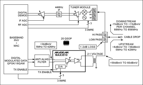
Block diagram of the MAX3510 upstream CATV amplifier system
Abstract: The block diagram in the article is the MAX3510 upstream CATV amplifier system. This design complies with the DOCSIS standard. The figure shows the transformer, tuner module, baseband IC, anti-spurious filter and duplexer.
The MAX3510 is a programmable power amplifier used in CATV upstream systems. This chip is the first product in the industry to comply with the DOCSIS standard. The following block diagram is a typical application system of MAX3510.
The MAX3510 can modulate carrier signals from 5MHz to 42MHz, and can provide harmonic characteristics better than -60dBc at 34dBmV output. A 2: 1 (transformer ratio) transformer can produce up to + 64dBmV (continuous wave) output. The operating frequency range is 5MHz to 65MHz. It is a variable gain amplifier controlled by a 3-wire digital serial bus. The gain control level difference is 1dB.
The MAX3510 provides a transmission inhibit mode. The chip is highly isolated between the burst modes of the TDMA system. In this mode, the output stage is turned off and the output noise is minimized. When entering or leaving the emission inhibit mode, the transient level is maintained at 7mV (typical) throughout the gain range. In addition, the power supply current is reduced to 25mA. 
DOCSIS cable modem
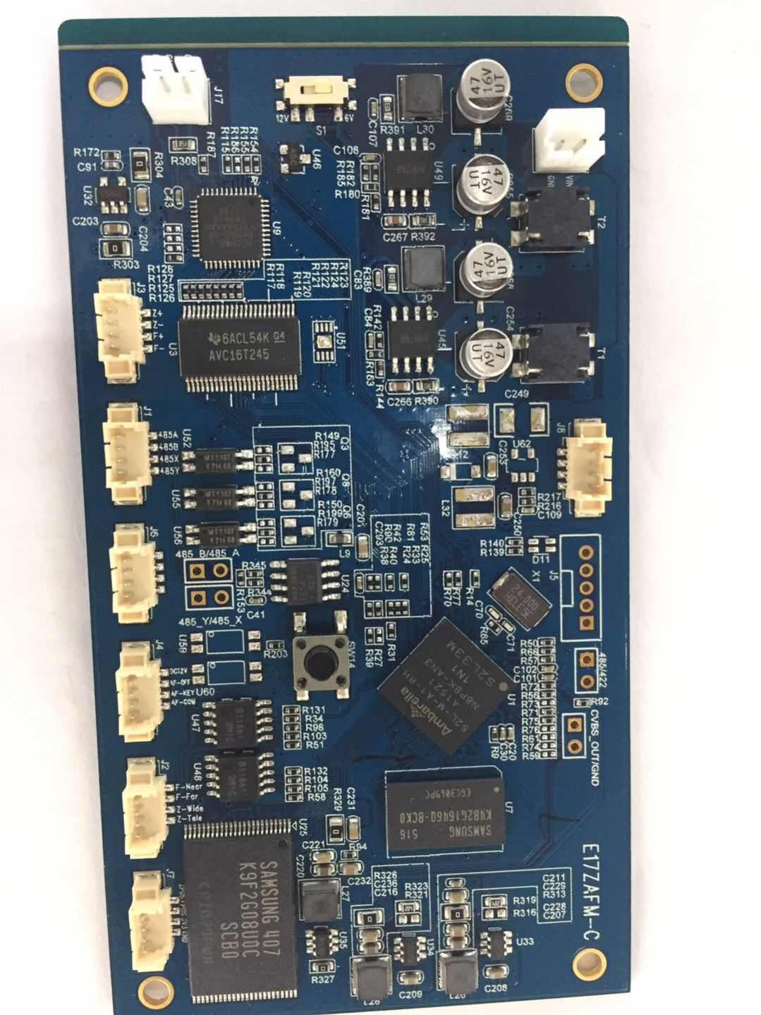
Printed Circuit Board assembly sometimes called PCB Assembly(PCBA).
The bare board is populated with Electronic Components to form a functional. In through-hole technology, the component leads are inserted in holes surrounded by conductive pads; the holes keep the components in place. In surface-mount technology (SMT), the component is placed on the PCB so that the pins line up with the conductive pads or lands on the surfaces of the PCB; solder paste, which was previously applied to the pads, holds the components in place temporarily; if surface-mount components are applied to both sides of the board, the bottom-side components are glued to the board. In both through hole and Surface Mount, the components are then soldered; once cooled and solidified, the solder holds the components in place permanently and electrically connects them to the board.

PCB Assembly
PCB Assembly,PCB Circuit Board ,Electronic PCB Assembly,Professional PCB Assembly
Orilind Limited Company , https://www.orilind.com