A typical fan controller provides PWM signal output to control fan speed. Under normal circumstances, the low-frequency signal (30~100Hz) controls the fan motor's on and off through the duty-cycle adjustable signal, so as to adjust the fan speed. Unfortunately, chopper control of the 3-wire fan (power, ground, and tachometer outputs) power supply constrains the tachometer signal (the feedback signal provided to the fan controller) because the signal is low during the low duty cycle. Cut off, thereby affecting the control loop. Some fan controllers try to compensate for these effects but they do not perform well. In addition, alternately switching the fan will produce "click" noise.
One solution is to use a low-pass filter to smooth the PWM signal and then use the smoothed signal to control the linear driver. For a 12V fan, the typical control voltage is 5~12V. An inexpensive linear regulator can be used to drive the fan. In addition, the circuit needs to introduce an RC filter circuit to smooth the PWM output and then amplify the current through an op amp buffer or an external regulator. This kind of scheme is feasible in principle, but if there is no extra protection will damage the circuit easily, once the short circuit of the fan will damage the whole circuit.
The universal linear regulator is ideal for fan-driven applications. The linear regulator consists of an operational amplifier, a pass transistor, a current limiter, a short-circuit protection circuit, and a high temperature protection circuit. All the functional circuits are integrated in a single package, and the price is very reasonable. What's more, the typical linear regulator can supply 0.5~1.5A current, which can meet most of the fan control requirements.
In a typical application, the controller applies a 100 Hz PWM signal to the base of the pass transistor, triggering the fan motor current on and off according to the PWM duty cycle, thereby controlling the fan speed. The circuit in Figure 1 uses a 100Hz PWM signal to control the fan. The PWM signal is provided by the open-drain output of U1 (dual-channel temperature monitor MAX6639 with two automatic PWM fan speed control outputs). This circuit does not control the on-off of the turn-on transistor, but uses the PWM signal shown in FIG. 1 to control the output voltage of the linear regulator (U2). The RC filter circuit smoothes the PWM output with a time constant equal to the product of the Thevenin equivalent resistance of R1, R2A, and R2B and the capacitance C1.
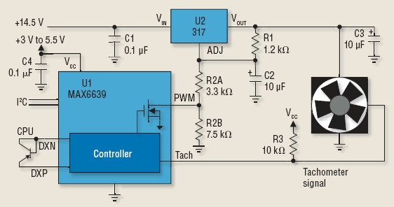
Figure 1: A simple, low-cost fan control circuit based on a linear regulator.
U2 regulates the output voltage to stabilize the voltage between VOUT and ADJ at 1.25V. Assuming that U1 does not affect the output, U2's output voltage is equal to 1.25V×(1+R2/R1), where R2=R2A+R2B. Assuming that U1's control role is to be considered, it should be noted that R2A determines the minimum output voltage. When the PWM polarity control bit of U1 is set to the positive duty cycle, the output with the duty cycle of 0% produces a very small PWM signal, making the open drain output continuous, equivalent to a short circuit to R2B. In this case, R2A (3.3kΩ) determines the minimum output voltage to be 4.7V. This voltage is already low enough to maintain an effective rpm signal while minimizing fan power consumption.
The sum of R2B and R2A determines the maximum value of VOUT. When the duty cycle is 100%, the open-drain output remains in the open state, R2B exhibits the maximum value in the voltage divider network, R2B of 7.5kΩ corresponds to the maximum voltage of 12.5V. C1 and C4 are typical bypass capacitors, C3 is U2's output capacitor, and C3 is used to smooth the output voltage and provide AC current to the fan.
The linear regulator drive scheme can provide effective speed control as well as high temperature and short circuit protection, but it consumes more power. For low-power fans, adding extra power may not be a problem, but high-power fans may not be able to handle the extra power consumption. When the voltage difference is 7V and the current is equal to 500mA, the regulator or the pass transistor needs to consume 3.5W, which will bring about heat dissipation. However, fans are often used to cool other circuits, rather than cooling the fan controller itself.
To find a more efficient and lower power management solution, consider switching regulators. Just like the linear regulator drive scheme described earlier, the switching regulator scheme requires smoothing and level shifting of the low frequency PWM signal output by the fan controller. The temperature monitor here still selects the MAX6639.
Switching regulators have a variety of topologies and suppliers, so choosing the right switching regulator is not easy. The range of choices for the application of this paper can be greatly reduced, because the switching regulator used here has some special requirements: First, it must be a step-down type, can drop the voltage of a 12V laptop battery or external battery to 5V; second, it must It provides current limiting protection when the fan is short-circuited, withstands high voltages when connected to a charger, and has an internal driver transistor and a simple voltage feedback circuit. Based on these criteria, we chose the MC33063A (U2) as shown in Figure 2.

Figure 2: High-efficiency fan control circuitry based on switching regulators.
U2 is configured as a conventional buck regulator because the circuit uses on-chip transistors, so it must be guaranteed that the peak current is below a certain limit of 1.5A. The peak current of the buck design is Ipk=2IOUT, so IOUTMAX must be limited to 750mA. R3 is used to limit the peak current, R3 = 0.3V/Ipk. When R3 = 0.5Ω, the peak current is limited to 600mA, allowing the use of a smaller current rated inductor and a common 1A Schottky diode.
In order to eliminate the audible noise, it is required to select an appropriate C1 and set the oscillation frequency of the switching regulator within the ultrasonic frequency range (50 kHz). The 50kHz oscillation frequency provides higher efficiency without using large size inductors. Considering the minimum output voltage is 5V, choose L1 to be 50μH.
The output voltage of the fan is VOUT=1.25V×(1+R2/R1), where R1 is the parallel resistance of R1A and R1B. The output of U1 is an open-drain signal of 100 Hz. When the duty cycle is equal to 100%, the PWM output turns off the open-drain output transistor, which disconnects R1B from the circuit. At this time, the fan voltage is VOUT=1.25V×(1+3.6kΩ/1.2kΩ)=5V. When the duty cycle is 0%, the PWM output is low, R1 is the parallel resistance of R1A (1.2kΩ) and R1B (600Ω), equal to 400Ω, and the fan voltage is VOUT=1.25V[(1+3.6) kΩ)/400Ω]=12.5V.
The actual output voltage will be slightly reduced because U1's PWM output is not referenced to true ground. The actual reference voltage is the output transistor's on-resistance, Rds, times 2mA (ie, the reference voltage at 1.25 on U2 divided by 1.25V divided by R1B. The resistance of 600Ω). According to the above discussion, when the duty cycle is 0%, the output voltage is 12.5V; when the duty cycle is 100%, the output voltage is 5V. It is also generally possible to use control bits to reverse the output polarity of the PWM to easily achieve the opposite result.
However, when the duty cycle is 50%, the C4 smooth PWM output. Large capacitance helps reduce ripple but increases response time. To balance the response time and ripple specifications, a 1μF capacitor is recommended.
When the voltage on pin 5 exceeds 1.25V, U2's hysteresis feedback signal will turn off the output. Due to the simple RC filter circuit, when the C4 voltage exceeds U2's reference voltage, the output can be turned off at a duty cycle of 50%. This effect can be compensated by increasing the output capacitor C2. C2 supplies fans with a negative cycle. To select the correct value of the capacitor, an experiment must be performed because this value is related to the minimum voltage at which the tachometer operates, the minimum duty cycle, fan noise, and other factors.
In Figure 2, based on a minimum duty cycle of 10% and a 1V output ripple voltage, the value of C2 is chosen to be 470μF, which absorbs 175mA at 12V. Of course, it is also possible to choose a capacitor with a larger capacitance, but the cost is high and the size is large. Most fans usually allow a certain amount of voltage ripple, the key is not to make the fan drive voltage is too low, so that the tachometer work is not guaranteed, or the fan voltage regulation produces noise.
Finally, it should be emphasized that the circuit of Figure 2 is more efficient than the circuit of Figure 1 when adjusting fan speed. Figure 3 compares the efficiency of these two circuits.
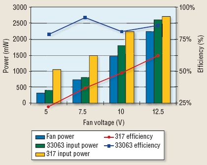
Figure 3: Comparison of linear regulator-type fan control efficiency (green) and switching fan control efficiency (purple).
Internally Installed Digital LED Strip puts main part of the driver IC is integrated into the commonly used 5050RGB patch lamp bead.
The advantage is that the circuit is integrated into the led bead, the external circuit can be omitted, and reduce the circuit design,
reducing external components, reducing the volume and reducing the production cost.
Control circuit and RGB chip is integrated into a 5050 packaged component to form a complete external control pixel.
The three primary colors of each pixel can achieve 256 levels of brightness display, serial cascade interface,
and can receive and decode data through signal lines. The color of the light is highly consistent and cost-effective.
Generally used for LED full color luminous word string, LED full color module, LED full color soft light strip hard light strip,
Led Pixel Screen, LED shaped screen and so on. It is one of the most common ribbons on the market.
Internally Installed Digital Led Strip
Digital LED Strip,5050Rgb LED,LED Strip Light Waterproof,Internally Installed Digital LED Strip
SHEN ZHEN SEL LIGHTING CO.,LTD , https://www.sel-lighting.com