Introduction <br> End-users are increasingly demanding fast charging and efficient charging. Lithium-ion (Li-Ion) batteries are an ideal choice because of their very high energy density. This battery has a high charging current and is well suited for 10 foot tablet applications and can be used for high battery capacity above 6 Ah. Tablets require excellent thermal performance and fast turn-on characteristics, even for deeply discharged batteries. These requirements present a number of design challenges for designers. The first is that if you maximize the effective power of the power supply, you can charge the battery efficiently and quickly while the power supply cannot crash. The second is how to charge the deeply discharged battery while the system is still running. Finally, how to improve the heat dissipation performance.
Dynamic Power Path Management <br> How to maximize effective power for fast, efficient battery charging? All power supplies have their output current or power limit. For example, the high-speed USB (USB2.0) port has a maximum output current of 500 mA, while the SuperSpeed ​​USB (USB3.0) port has a maximum output current of 900 mA. If the system power demand exceeds the effective power of the power supply, the power supply will crash. When charging the battery, how do we prevent the power supply from collapsing while maximizing the power output? We used three control methods: input current type DPM, input voltage type DPM, and battery replenishment mode.
Figure 1 shows a high efficiency switch mode charger using DPM control. MOSFETs Q2 and Q3 and inductor L form a synchronous switching buck battery charger. This composition method achieves the highest battery charging efficiency and makes full use of the adapter power, thus achieving the fastest battery charging. MOSFET Q1 acts as a battery reverse blocking MOSFET to prevent battery leakage from flowing through the MOSFET Q2 body diode to the input. In addition, it is used as an input current sensing component to monitor the adapter current.
MOSFET Q4 is used to actively monitor and control the battery charging current to achieve DPM. The ICHG ideal charging current value is used to charge the battery when the input power is sufficient to support both system load and battery charging. If the system load ISYS suddenly increases and its total adapter current reaches the current limit setting IREF, the input current regulation loop actively regulates and maintains the input current at the predefined input reference current IREF level. This can be achieved by lowering the charging current and prioritizing the system to achieve maximum system performance. Therefore, the input power can always be maximized without the input power source crashing, while the effective power is dynamically shared between the system and the battery charge.

Figure 1 Input current type dynamic power management
If the system is connected to a third party can not recognize that the current limit of the power supply, it is difficult to use the DPM-limited input current, input voltage type and use the DPM, control algorithm shown in Figure 2. Resistor dividers R1 and R2 are used to sense the input voltage and provide an input to the error amplifier of the input voltage regulation loop. Similarly, if the system load increases, causing the input current to exceed the adapter current limit, the adapter voltage begins to drop and eventually reaches a predefined minimum input voltage.
The input voltage regulation loop is activated to maintain the input voltage at a predefined voltage level. The charging current is automatically reduced so that the total current from the input supply reaches its maximum value and the input supply does not collapse. Therefore, the system can now track the maximum input current of the adapter. This method is used to design the input regulation voltage, which is still high enough to fully charge the battery. For example, it can be set to around 4.35V to fully charge a single-cell Li-Ion battery pack.
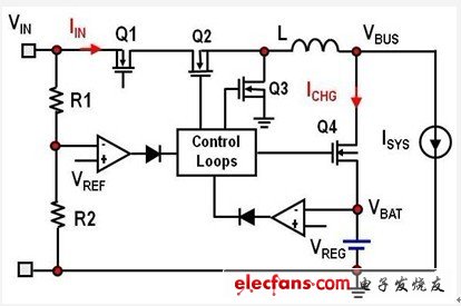
Figure 2 input voltage type dynamic power management
Both input current and input voltage type DPM control can get maximum power from the adapter without crashing the adapter. For portable devices such as smart phones and tablets, system loads typically change dynamically with high ripple currents. Even if the charging current has dropped to zero, what happens if the peak power of the pulsating system is higher than the input power? Input power may crash without active control.
One solution is to increase the rated power of the adapter, but this will increase the size and cost of the adapter. Another option is to supplement the system with additional power in addition to the effective power provided by the adapter to temporarily discharge the battery. Therefore, the battery turns on MOSFET Q4 to provide additional power to allow the battery to discharge and charge. The combination of DPM control and battery replenishment power mode optimizes the adapter to support average power rather than maximum peak system power for cost reduction and minimum solution size.
The FTTH Installation Accessories Set concludes junction box, fiber wall socket(also named Single family unit rosette, SFU rosette), draw hooks, cable clamp, cable wall bushings, cable glands, cable clips, tail duct, cable wiring duct, nail clip.
Cable drawing hooks are made of metal stainless steel in accordance with ASTM A307.hanging hardware, hard material, with splint type and C type for option. The conduit box, pipe joint box single gang or double gang are made of PC material, fire retardant.
Applications:
Span Clamp is attached to the messenger wire at mid span to hold the p-clamps with drop wires
Telecommunications subscriber loop
Fiber to the home (FTTH)
LAN/WAN
CATV
Drop Wire Hanging Holder,Drop Wire Hanging Holder,Cable Pole Clamp,Cable Fitting Clamp are available.


FTTH Cable Installation Accessories
Drop Wire Hanging Holder,Drop Wire Hanging Holder,Cable Pole Clamp,Cable Fitting Clamp
Sijee Optical Communication Technology Co.,Ltd , https://www.sijee-optical.com