One of the key differences between the CAN protocol and other fieldbus protocols is its use of synchronous data transfer rather than asynchronous transfer for individual characters. This approach allows for more efficient transmission performance, but it also requires a more sophisticated bit synchronization mechanism. Unlike asynchronous protocols, where each character has a start bit that helps align the receiver, CAN uses a single start bit at the beginning of a frame. This makes maintaining synchronization between the transmitter and receiver more challenging.
In character-oriented protocols, synchronization is relatively straightforward because the start bit of each character acts as a reference point. However, in CAN, since there's only one start bit per frame, the receiver must continuously resynchronize during the transmission to maintain timing accuracy. Resynchronization involves detecting signal edges in the bit stream and adjusting the sampling point accordingly. During the longest time between signal edges, the receiver must account for potential timing differences between the transmitter and itself by using a "phase buffer segment" before and after the nominal sampling point within each bit interval.
Because CAN employs non-destructive bit arbitration and explicit acknowledgment bits, the signal must travel from the transmitter to the receiver and back within a single bit time. This necessitates additional time for signal propagation on the bus and internal node delays. To accommodate this, a "Transmission Delay Segment" is included in the bit time, ensuring that all nodes have enough time to process the signal correctly.
Figure 1 illustrates the nominal bit time, which is divided into four non-overlapping segments:
- Sync_Seg (Synchronization Segment)
- Prop_Seg (Propagation Segment)
- Phase_Seg1 (Phase Buffer Segment 1)
- Phase_Seg2 (Phase Buffer Segment 2)
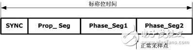
Figure 1: Bit Time Division
The length of the bit time is determined by a basic time unit (tq), which depends on the oscillator frequency. The synchronization segment is crucial for defining the timing reference. The distance between the edge generated after the sync segment and the sync segment itself is called the "phase error e." This phase error determines how much adjustment is needed during resynchronization.
The transmission delay segment accounts for the maximum signal propagation delay in the network. It should be twice the sum of the maximum delay between two nodes plus their internal processing times. This ensures that the signal arrives on time for accurate sampling.
There are two types of synchronization in CAN: "hard sync" at the beginning of a frame and "resync" during the frame. After a hard sync, the bit time restarts regardless of the phase error. Resynchronization adjusts the bit time by shifting the sampling point forward or backward, depending on the detected edge.
The idle time in the phase buffer segments allows for adjustments during resynchronization. Synchronization occurs only when a recessive-to-dominant bit transition is detected. If an edge is found within the sync segment, it is synchronized; otherwise, the phase error is calculated based on the distance to the end of the segment. A positive phase error means the edge arrived later than expected, while a negative one means it arrived earlier.
If the phase error is less than or equal to the programmed "synchronous jump width" (SJW), the sampling point is adjusted accordingly. If the phase error exceeds SJW, some residual error remains. Only one synchronization can occur between two sampling points, ensuring stable communication and filtering out minor fluctuations.
Each segment of the bit time can be configured within certain limits:
- Sync_Seg: 1 tq
- Prop_Seg: 1–8 or more tq
- Phase_Seg1: 1–8 or more tq
- Phase_Seg2: Max{Phase_Seg1, data processing time}
- Baud rate prescaler: 1–32
- SJW: 1–4, not exceeding Min{4, Phase_Seg1}
During resynchronization, Phase_Seg1 may be extended, and Phase_Seg2 may be shortened. The data processing time starts after the sampling point and represents the time used to determine the next bit to transmit. It must not exceed two tq and serves as the lower limit for Phase_Seg2.
The time share value for each bit time must be set between 8 and 25 tq. This ensures sufficient resolution for accurate timing and synchronization across the network.
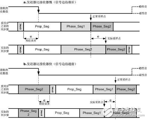
Figure 2: Principle of Resynchronization
As shown in Figure 2, if the transmitter’s oscillator is slower than the receiver, the signal edge will arrive late. The receiver compensates by shifting the sampling point. The maximum phase error that can be corrected is limited by the length of Phase_Seg1. If the phase error is less than or equal to SJW, the sampling point is adjusted accordingly. If the transmitter is faster, the signal edge arrives early, and the second phase buffer segment is shortened to adjust the timing.
The phase buffer segments are temporarily adjusted and return to their nominal values if no further phase errors are detected. The receiver expects the edge to appear in the sync segment. If no edge is found, the sampling point remains at its default position.
According to ISO 11898-1, the following rules apply to bit synchronization:
- Only one synchronization can occur between two sampling points in a single bit time.
- Synchronization from recessive to dominant signal edges is allowed only when the previous and current samples differ. Short pulses do not trigger synchronization.
- Whenever a recessive-to-dominant edge is detected on an idle bus, a "hard sync" is performed, starting a new bit interval.
- During the interframe space (excluding the first bit of the frame), a recessive-to-dominant edge triggers a hard synchronization.
1. Glass: Glass insulators are known for their high resistance to electrical conductivity and durability.
2. Porcelain: Porcelain insulators exhibit excellent electrical insulating properties and mechanical strength, making them suitable for various voltage levels.
3. Ceramics: Ceramics, including advanced composite materials, are chosen for their high resistance and ability to withstand harsh environmental conditions.
4. Rubber: Rubber insulators are flexible and provide good electrical insulation, often used in applications where flexibility is required, such as in some types of cables and connectors.
Insulators,Insulator Dead End Polymer,Long Rod Silicone Rubber,Composite Suspension Insulator
Shahe Yipeng Import and Export trading Co., LTD , https://www.yppolelinehardware.com