The goal of this paper is to develop a wheeled car inertial navigation system, which can realize the PC terminal and the handheld terminal to control the wheeled car action and the data collected by the car through wifi. Set up the system shown in Figure 1 below. TI's floating-point DSP TMS320F28335 ($16.0312) chip is used as the main digital signal processor to collect and process the signals of each MEMS inertial sensor. The processing result is transmitted to the PC terminal through WIFI; PC terminal Responsible for displaying the positioning result and map display, and sending control commands to the trolley drive system, while receiving the odometer information fed back by the drive system.
This article refers to the address: http://
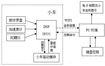
Figure 1 Overall architecture
Hardware design, mainly divided into core board and driver board. The core board includes DSP minimum system, JTAG download port design, system power supply circuit and MEMS sensor, WIFI module and so on. The main design of the driver board is the drive module of the DC motor.
Power circuit design
The TMS320F28335 requires different voltages during operation: the core voltage (1.9 V) and the I/O supply voltage (3.3 V), which are sensitive to the power supply, so the power supply is implemented using two output power devices TPS767D318 ($2.3625), as shown in Figure 2. Show. At the same time, according to the simulation experiment and the actual welding circuit test, it is better to use some protective capacitors with a capacitance value of not less than 10uf, and the chip capacitor cannot be used, otherwise the operation is unstable.
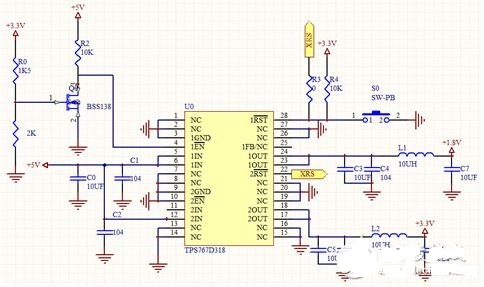
Figure 2 DSP power supply design
In the power supply design, considering that the TPS767D318 chip can generate a reset signal, there is no additional reset circuit for the DSP on the core board.
JTAG download port circuit design
Figure 3 shows the JTAG circuit. Select the 14-pin emulation interface according to the emulator's communication pin. Also note that the EMU0 and EMU1 signals must be connected to the power supply through pull-up resistors, where the pull-up resistor is 10kΩ.
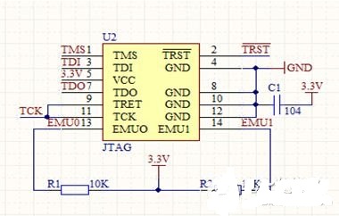
Figure 3 JTAG circuit design
Car drive board design
In this device, we use the BTS7960 as the DC motor driver chip. The BTS7960 is an integrated high-current half-bridge driver that contains an NMOS, a PMOS, and a half-bridge gate drive. It has an internal impedance of 17mΩ at IOUT = 9 A, VS = 13.5V, and Tj = 25 °C. . The device uses two DC large motors, as shown in Figure 4, which is a circuit diagram that drives the front and rear steering of a single motor.
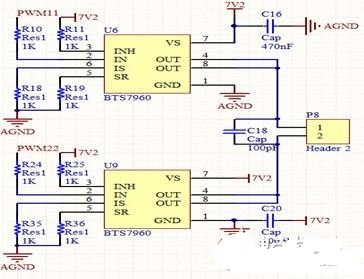
Figure 4 drive module circuit design
In the motor drive here, you need to pay attention to a detail, that is, the motor may generate a reverse electromotive force during the rotation process, so that the current is too large, causing the microcontroller to reset or even burn the chip. Therefore, in the design process, you can consider adding optocoupler isolation or diode at the PWM input to the motor drive interface. As shown in Figure 5, the driver board selects the optocoupler design isolation circuit of tlp521-4 ($0.5320) to reduce the voltage interference, reduce the design of the circuit, and also the I/O level of the four PWMs. 3.3 Pull up to 5V.
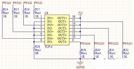
Figure 5 TLP521 ($0.1403) isolation circuit
The wheeled trolley indoor inertial navigation device designed in this paper analyzes the specific implementation methods of each module of the software design. The experimental results show that the design can monitor the position information of the mobile robot in real time and can effectively control it. At the same time, its low-cost, high-precision and easy-to-operate features will be further applied to professional fields such as patrol robots and rescue robots. It will attract many investors from home and abroad to invest in it and carry out further research and development and application. A vast majority of innovation and entrepreneurial prospects, application prospects and market prospects.
The insert splitter is used for the user access point in the FTTX system, which mainly completes the optical fiber end of the residential area or building, and has the functions of optical fiber fixation, stripping, fusion, jumper and shunt, etc. After the splitter, it enters the end user in the form of household optical fiber.
There are currently 1 x N and 2 x N.1 x N and 2 x N evenly inputs the optical signal from a single or double inlet into multiple outlets, or work backward to integrate multiple optical signals into a single or double fiber.
PLC Insert Splitter,Insert Splitter,PLC Optical Splitter,PLC Fiber Splitter
Chengdu Xinruixin Optical Communication Technology Co.,Ltd , https://www.xrxoptic.com