Session initiation protocol SIP is the core technology for providing multimedia services in 3G's IP multimedia subsystem. The article first introduces the basic working principle of SIP, then briefly describes the IMS defined by 3GPPUMTSR5, and finally details the process of SIP providing services in IMS and the treatment of roaming users.
The session initiation protocol (sessioniniTIaTIonprotocol) is a signaling control protocol defined by the IETF to implement real-time communication applications based on IP networks. 3GPP has defined the IP Multimedia Subsystem (IPMulTImedia Subsystem: IMS) network architecture, and is based on SIP to carry various multimedia services (VoIP, streaming media, online games, etc.).
1. Introduction to SIP
Session Initiation Protocol SIP (SessionIniTIationProtocol) is described to generate, modify and terminate the conversation between one or more participants. It is a signaling proposed by the IETF in 1999 to implement real-time communication applications based on IP networks Control protocol. It breaks the transmission mode of traditional telecommunications services, adopts Internet-based guidelines, and integrates cellular systems with Internet applications to provide IP-based multimedia services. It has the characteristics of openness, scalability, and security. 3GPP
SIP has been used as the control protocol for the multimedia domain of the third generation mobile communication system.
It often happens that a user moves between multiple locations. For example, a company employee may be in a company, home, or cafe. In order to provide users with convenient mobility, SIP uses Uniform Resource Identifier (URI) to represent users. It usually consists of a domain name plus a user name, such as SIP: John@eastcom.com, similar to an email address. The SIP URI is just a logical identifier used to uniquely identify the user. When the user registers, it will be bound to the user's IP address and recorded to the location server.
In SIP, the system adopts the client / server structure commonly used in the Internet, which is composed of two parts: user agent and server. The user agent is divided into two types: user agent client (UAC: UserAgentClient) and user agent server (UAS: UserAgent Server). UAC is used to initiate session requests, and UAS is used to accept and respond to session requests. These two are only logical functions. In fact, the network terminal should have these two functions at the same time, both to initiate a conversation, and to accept and respond to the conversation. The server is divided into a proxy server (Proxy Server), a redirected server (Redirected Server) and a registration server (Registrar).
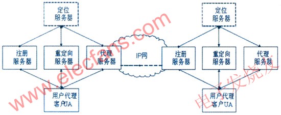
Figure 1 SIP network architecture
Figure 1 describes the basic network architecture of SIP. After the user accesses the network, he must first register with the registration server, and the registration information is written into the location server (the location server is not a SIP network element, but only a database). When the user agent client UAC wants to initiate a call, it generally sends a call request message to the outgoing proxy server in this domain. The media description information is encapsulated in the SIP message body in the form of SDP (SessionDescriptionProtocol) and sent out. The proxy server checks the called address and forwards the request (possibly through multiple intermediate proxy servers) until it reaches the proxy server in the called domain. The proxy server of the called domain determines the exact location of the called by querying the positioning server, and then forwards the request to the called user proxy server UAS. After receiving the request, the called UAS generates a response message. The response message will be returned to the calling UAC in the same way as the request message. Based on the content of the response message, the calling UAC chooses to establish a call, re-initiate the call, or cancel the call. If the called party is not at home, the calling party will relocate the called party through the relocation server and then initiate the request.
SIP has two types of messages:
(1) Request: A message sent from the client to the server. The SIP core specification defines 6 types of SIP requests:
INVITE—Invite users to join the call.
BYE-Terminate the call between two users.
OPTIONS—Request information about server capabilities.
ACK—Confirm that the client has received the final response to INVITE.
REGISTER—Provides address resolution mapping to let the server know the location of other users.
INFO—Used for signaling in the session.
(2) Response: A message sent from the server to the client. When the server receives the request, it sends one or more responses. Each response has a status code (integer of 100-699) that represents the status of the transaction. The following are the commonly used responses and their status codes:
trying (100)-trying
ringing (180) —ringing
sessionprogress (183) —session progress
OK (200)-good
2. The basic structure of IMS in 3GPP R5
According to the definition of 3GPP, the 3G network is divided into three domains: circuit-switched domain, packet-switched domain, and IP multimedia domain (see Figure 2).

Figure 2 3GPP R5 basic structure
The circuit-switched domain is similar to the existing 2G network and uses circuit-switched technology to provide voice services. The packet switching domain is introduced in the 2.5G network, and the main network element devices are SGSN (ServiceGPRS SwitchNode) and GGSN (Gateway GPRS Switch Node). They are responsible for providing an IP connection to the terminal. The user enters the Internet through this domain, from which the user can send emails and browse the web. It does not define any special architecture above IP, it is mainly an access technology. The IP multimedia domain (ie, IMS, IP MulTImedia Subsystem) was introduced in the UMTS R5 version formulated by 3GPP, and uses SIP as the main signaling protocol, so that mobile operators can provide end-to-end all-IP multimedia services for users.
IMS consists of call state control function CSCF (CallSessionControlFunction), media gateway control function MGCF (Media Gateway Control Function), media gateway MGW (Media Gateway), home user server H
SS (Home Subscriber Server) and other functional entities. The types of CSCF include P-CSCF (Proxy-CACF, Proxy CSCF), I-CSCF (Interrogating CSCF, Query CSCF), and S-CSCF (Serving CSCF, Serving CSCF). In essence, they are all SIP servers and handle SIP signaling. .
â— P-CSCF is the first step for the UE to contact IMS. It is the first point that the UE must visit in the visited domain (when roaming). The incoming and outgoing SIP messages must pass through the P-CSCF. P-CSCF is equivalent to the border proxy server defined by the SIP protocol.
â— The function of I-CSCF is to provide an entrance to the home network, hide the topology map of the home network from other networks, and find the corresponding S-CSCF for specific users through HSS. It is the point of contact where user terminals roam or external tasks enter the local service provider network. When the I-CSCF receives a request, it will route the request to the corresponding S-CSCF.
â— S-CSCF provides services to users. When the terminal registers, it contacts the S-CSCF of the local domain, and the local S-CSCF provides the user with the service predetermined by the user. The advantage of this is that even if users roam to a network that does not support a certain service, they can get the services they need as if they were local.
HSS (HomeSubscriberServer) is equivalent to the HLR in the 2G network, and stores the S-CSCF and the corresponding user profile related to a single user. Therefore it knows the user's current location and the service specified by the user. The CSCF can ask the HSS to obtain this information. The interaction between HSS and CSCF is the Cx interface, which is not formulated by the IETF, but is also based on IP.
3. User SIP registration
The user must complete the SIP service registration before initiating a session. UE (UserEquipment) will tell HSS where it is now, HSS updates the information of the corresponding user; before registration, to verify, HSS checks whether the user can be registered according to the user information and operating restrictions; in the service registration, the local domain must also be UE Select an S-CSCF and send user information to the S-CSCF. This process is completed at the application layer, so a signaling link must be established before registration. Therefore, the links from UE to SGSN and SGSN to GGSN must be established first. After this link is established, the user can register.
As shown in Figure 3, the whole process of a user's registration in the 3G network is described. After registration, the system will assign an S-CSCF to the user, and this S-CSCF is responsible for providing services to the user. First, the user sends a registration request from the UE to the local P-CSCF. P-CSCF is the point of contact between the UE and the network. The P-CSCF forwards the registration request to the I-CSCF where the user belongs. The home I-CSCF consults the HSS, and the I-CSCF selects an S-CSCF for the user based on the information about the user obtained from the HSS. Therefore, the original registration request can be handled by this S-CSCF. Once the request is received, the S-CSCF downloads the user's information from the HSS, which tells the S-CSCF which services the user has subscribed to. Eventually, it sends an agreed response signal.

Figure 3 Signaling flow of user registration
Fourth, the conversation between roaming users
Once the UE registers with an S-CSCF, voice and multimedia calls can be established. The process of establishing a link between two users is actually the process of traversing each CSCF. Generally speaking, it follows the route of "calling user â—‡ calling location P-CSCF â—‡ calling home S-CSCF â—‡ called home at S-CSCF â—‡ called home P-CSCF â—‡ called user".
The SIPCSCF server in the place where the user visits does not handle user services. It only plays the role of accessing the network and forwarding information. Providing service services to users and accessing other networks (such as PSTN) rely on the S- CSCF. When the user enters the network, he first registers with the P-CSCF of the visiting place, tells the P-CSCF where he belongs, just as if the foreign population arrives, he first registers with the visiting public security bureau to obtain a temporary residence permit, and registers who he is and where he resides . Next, it informs the home S-CSCF of its location through the visited P-CSCF and updates the location information in the HSS. When a user sends a session request, the visiting P-CSCF sends the request to the user's home and hands it over to the S-CSCF. Similarly, when a session request is sent to the user, the request first arrives at the home, and the home finds the user's After the location, contact the user through the P-CSCF where the user visits to establish a link.
As shown in Figure 4, it is the most common session establishment process for two roaming users. A complete IMS call is divided into five stages: session invitation, resource reservation, session provision, session connection, and session termination.
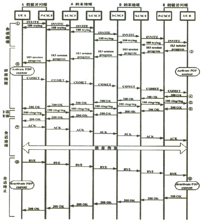
Figure 4 SIP signaling exchange for two roaming user sessions
The call process is as follows:
(1) Session invitation
A sends an INVITE request message to the P-CSCF. This message contains SIPURIs of B and A. P-CSCF notices that A does not belong to the local user and forwards the INVITE message to A's home and returns a 100 trying temporary response A (indicating that A's request has been sent and is trying to establish a link, A needs to wait). The local domain I-CSCF of A queries the HSS and forwards the INVITE to the S-CSCF allocated during A registration and returns 100 trying to the foreign P-CSCF. After receiving the request, the S-CSCF forwards the INVITE to the called B's local domain and returns 100 trying to the I-CSCF. Similarly, the I-CSCF where B belongs
After receiving the request, he queries the HSS and forwards the request to B's home S-CSCF. The S-CSCF finds that B is in the foreign network, so it forwards the INVITE to the P-CSCF where B is currently located, and then the P-CSCF Pass the request to B last.
(2) Resource reservation
B accepts the session request, but at this time he does not ring back to notify A. He returns a 183 session process response to indicate that he accepts the session, and asks A to confirm this. This response is passed to A through each CSCF. At the same time, B activates a GPRSPDP context, which is used to establish a voice channel through the IMS IP access point.
After receiving the 183 response, A also activates a PDP context and sends a COMET message to B through the channel established by the CSCF. This message contains the address details of A's voice channel and serves as a confirmation.
(3) Session provision and session connection
When receiving COMET, B knows that the IP channel and quality of service parameters for transmitting voice have been reserved by both parties, and knows the address of the voice channel, so B returns a 200OK confirmation message. This message contains the address details of B's ​​voice channel.
After receiving the confirmation, A gives B a 180 ringing message. When B hears the ringing, he sends A a 200OK message. Finally, A sends B an ACK confirmation message. When this communication link is established, A and B can proceed. Called.
(4) Session termination
In order to terminate the session, A sends a BYE message to B. At the same time A revokes his PDP context.
After B receives the BYE message, it will revoke its PDP context and return a 200 OK response to A for all CSCFs used by the house change call.
V. Conclusion
The SIP protocol is a simple and flexible protocol with strong inclusiveness, and a strong expansion mechanism is established on the basis of keeping its core protocol simple, so a large number of applications can be easily realized using SIP technology. We can undoubtedly say that 3GIMS based on SIP will bring a faster, richer and more flexible communication experience to users.
Function: The LED Aluminum Flashlight has 3-5 modes;
Feature: The LED Aluminum Flashlight usually high power and super bright;
Trait: The products are waterproof, shockproof and tactical;
Method of application: Simple on/off push button operation;
Range of application: The LED Aluminum Flashlight for emergency events, camping, outdoor activities and indoor;
Adervantages: Our products are saled with factory price, and the quality can guarantee, lastly we provide warranty for 1 year.
LED Aluminum Flashlight
Aluminum Led Flashlight,Aluminum Torch,Electric Focus Led Flashlight,Aluminum Portable Lights
Ningbo Henglang Import & Export Co.,Ltd , https://www.odistarflashlight.com