1 Introduction
Informatization has become a major trend in social development. Informatization is based on digitalization, and DSP technology is one of the most important basic technologies of digitalization. The DSP processor is a microprocessor specially designed for high-speed digital signal processing. Compared with many general-purpose CPUs and microcontrollers (MCUs), DSP processors have adopted many specialized techniques and measures to improve processing speed. The DSP processor is different from the general-purpose microprocessor. It does not use the Von Neumann Architecture (Von Neumann Architecture) that shares the program code and data with a common storage space and a single address and data bus, but without exception. The storage space for program code and data is separated, each has its own address and data bus, the so-called Harvard Architecture, which increases the data exchange capability of the processor.
OFDM (Orthogonal Frequency Division Multiplexing) is a kind of multi-carrier modulation technology implemented directly using discrete Fourier transform (DFT). It uses parallel transmission to decompose and modulate the transmitted high-speed data into multiple intersecting In the overlapping and orthogonal sub-channels, the symbol width of each sub-channel is greater than the spreading delay. If a certain length of guard interval is added between the symbols, the inter-symbol crosstalk caused by multipath transmission is basically eliminated. The above-mentioned characteristics of OFDM make it particularly suitable for transmitting high-speed data in mobile wireless transmission channels with multipath propagation and Doppler frequency shift. Currently used in power line communications, digital sound broadcasting (DAB) and European high-definition television transmission standards (DVB-T), wireless local area network (WLAN) and other services.
Based on the overall block diagram of the system, the paper implements the design of the OFDM baseband system on TMS320C5509DSP and gives specific performance indicators.
2. Design and implementation of OFDM system
2.1 The flow chart of the task to realize the system
The system can transmit 56 bits of effective information per frame, and the data transmission rate will reach 100 kbit / s. In order to reduce the unsatisfactory channel during transmission, BSPK is used to encode and map the source. In the transmission process, the transmitted It is a time-domain signal, but what is actually useful is the frequency spectrum of these time-domain signals. These signals are random random signals in the time domain, but each sub-carrier in its frequency spectrum carries the information to be transmitted. The working block diagram is shown in Figure 1:
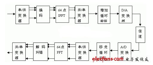
Figure 1. System task block diagram
The whole system is completed by DSP and FPGA, D / A, A / D and some other hardware. The task flow is that the DSP accepts the parallel data converted by serial / parallel, encodes the BPSK source in the DSP, maps 0 and 1 to two hexadecimal numbers 0xbffd and 0x3fff, and then sends it to the IFFT unit Change to the time domain for processing, and then add the cyclic prefix to the data, send it to the FPGA for processing, and the FPGA will send the data to the receiving board. After receiving data from FPGA on the receiving board for a series of processing, the data is serially transmitted to the DSP of the receiving board. The received data is removed from the cyclic prefix on the DSP of the receiving board, and sent to the FFT unit to restore the data to the frequency domain, and then judged with a threshold of 0, and the earliest original data is obtained after the mapping.
2.1 Detailed task flow
The original data carries 56 bits of binary information per frame (that is, only two values ​​of 0 and 1). In the block diagram, the D / A and A / D parts are completed by special hardware. The project uses ADS828e and DAC902u.
Send part:
We used BPSK for the source coding part, in order to further increase the Euclidean distance between the signals. Through calculation, we decided to choose two hexadecimal numbers 0xbffd and 0x3fff to represent 0 and 1 respectively. Since the FFT transform requires the data to be 2N data, the data is inserted into several zeros to make up. The specific method is to insert seven zeros at the 28th data position after the mapping. Since there can be no signal at zero frequency (in order to have no DC component), no information is transmitted at the beginning of the frame, the first number is inserted into zero (not 0xbffd), and 56 numbers are changed to 64 numbers. The 16 numbers in the same position are removed.
The 64-bit IFFT is performed on the 16-bit numbers after coding and mapping, and the data is transformed from the frequency domain to the time domain, waiting for the next processing.
In the OFDM system, in order to prevent multipath delay, cyclic prefixes must be added, and these cyclic prefixes cannot destroy the orthogonality between sub-channels, so the last 16 digits are brought forward to form 80 numbers. The specific method is that after IFFT is completed, the cyclic prefix must be added to send the data to the FPGA. The last 16 bits of the data are copied to the beginning of the data (the original 16 numbers are not moved), and the data is changed to 80 and sent to The serial port is sent to the FPGA.
After FIR filtering on the FPGA and a series of processing, the task of the sending board is completed, and then the data is sent to the receiving board.
Receiving part:
The FPGA receives the data sent by the sending board, and after a series of processing, the data is serially sent to the DSP for further processing.
After the DSP on the receiving board receives the 80 serial data from the FPGA, it first removes the cyclic prefix, that is, removes the first 16 digits, and turns the 80-bit data into 64-bit, which is then processed by the next step.
After the data is changed back to 64 bits, the data is subjected to FFT transform, from the time domain to the frequency domain, and then handed over to the next step for processing.
Before making a decision, you must first remove the inserted 16 numbers, change the 64-bit number to 56-bit, and then make a decision. One advantage of BPSK is that you can directly use zero as the threshold when making a decision. After the judgment, the data is restored to the original initial test value.
In summary, in the DSP part, there are 10 tasks,
Sender
1. BPSK encoding and inserting data (the number of data is changed from 56 to 64)
2. Make an IFFT transform of N = 64 to change the data in the frequency domain to the time domain.
3. Add cyclic prefix (the number of data changed from 64 to 80) to prevent multipath delay.
4. Send data to Mcbsp to FPGA through DMA.
Receiving end
5. The data received by Mcbsp is stored in the data space through DMA (at this time the data should be the same as the end of the fourth step).
6. Remove the cyclic prefix (the number of data is changed from 80 to 64, and the data should be the same as the end of the third step)
7. Make 64-point FFT transform (the result should be the same as the end of the first step)
8. Remove the inserted data, reverse mapping (the number of data is changed from 64 to 56, and the result should be the same as the beginning of the first step) and decode.
The Metal Convection Heater warm the room as it passes over a heated coil; some use a fan to forced in the cool air to heat. The heated air rises naturally or is forced out by a fan and spreads into the space to warm room.
A metal convection heater is a type of heater that uses convection currents to heat and circulate air. These currents circulate throughout the body of the appliance and across its heating element.
Convector Heater including glass convection heater, metal convection heater, also mini convector heater can be a Frost Heater.
welcome to OEM,thank you
Metal Convection Heater
Gas Convector Heater,Dura Heat Convection Kerosene Heater,Small Convector Heaters,Portable Convection Heater
Fenry manufacturing Co., Ltd , https://www.cnfenry.com