Why can't I see the waveform or waveform distortion when I use the oscilloscope to observe the waveform of the crystal pin? Isn't the 200M oscilloscope unable to measure the 10M crystal?
Common crystal oscillator
First, let's briefly introduce the crystal oscillator. The crystal oscillator can be roughly divided into two categories: passive crystal oscillator and active crystal oscillator.
2, passive crystal oscillator
A passive crystal oscillator is a non-polar component that requires a clock circuit to generate an oscillating signal and cannot oscillate itself. Passive crystals have no voltage requirements, and the signal level is variable, that is, determined by the start-up circuit.
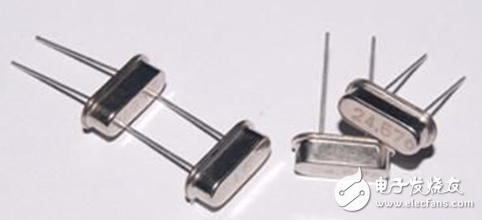
Figure 1 Passive crystal oscillator
3, active crystal oscillator
The active crystal oscillator is a complete oscillator with a transistor and a RC component in addition to the quartz crystal. The active crystal oscillator does not require an internal oscillator, the signal quality is good, stable, and the connection method is relatively simple, and does not require complicated configuration circuits.

4. Crystal waveform analysis
The crystal oscillator waveform is generally a sine wave or a square wave. When the output waveform is a square wave, the general rising edge is relatively jittery and contains more high frequency signals. At this time, it is necessary to ensure that the bandwidth of the test is sufficient. The theoretical value is that the bandwidth is When measuring the frequency of the signal twice, the actual test square wave bandwidth should be 10 times the frequency of the measured signal.
In addition to the bandwidth, when testing the crystal oscillator, there is one more point to note: the crystal oscillator is sensitive to the capacitive load, and the probe capacitance is relatively large, which is equivalent to a very heavy load connected in parallel in the crystal oscillator circuit, which easily leads to the circuit being stopped. No correct measurement results.
Therefore, when performing the crystal test, it is necessary to ensure sufficient bandwidth and a small input capacitance.
5. The correct way to test the crystal oscillator
First of all, let's answer the question of the title. The 200M oscilloscope can definitely test the waveform of the 10M crystal, but why is the measured waveform the shape of Figure 3?

Figure 3 Distorted crystal waveform
This is because during the test, the probe selected &TImes;1 gear, the ZDS1025S probe of the ZDS2000 series standard has a bandwidth of 10MHz in the &TImes;1 gear, and the input capacitance is 55 pF±10 pF, which causes distortion of the waveform. .
Table 1 ZP1025S technical parameter table
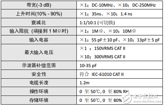
Let's adjust the probe gear position to &TImes; 10 files. At this time, the probe bandwidth is 250MHz and the input capacitance is 13pF±5 pF. Let's take a look at the waveform at this time.
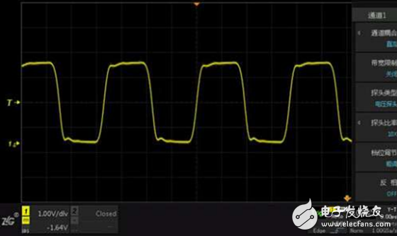
Figure 4 correct crystal waveform
In order to improve signal fidelity, you should also use the grounding spring that comes standard with the probe instead of grounding the alligator clip to ground.

Figure 5 Standard grounding spring
When you use the oscilloscope for testing, in addition to paying attention to the oscilloscope settings, you should also pay attention to the current probe gear position, different gears correspond to different parameters, the right is the best!
FGI SCIENCE AND TECHNOLOGY CO., LTD , https://www.fgi-tech.com