Through in-depth research and analysis of digital potentiometer chips, combined with the needs of the low-cost market, we have developed hardware and software platforms, designed mixed-signal system circuits, and expanded the application scope of digital potentiometers. This article discusses the working principle, characteristics, classification, and wide-ranging applications of digital potentiometers. It highlights the advantages of digital potentiometers over traditional mechanical ones, such as higher accuracy, no physical contact, and better stability. The internal structure of the AD5272 digital potentiometer is also explained in detail, followed by a practical design of an application circuit system using this chip. The results demonstrate that digital potentiometers offer excellent performance at a low cost, proving to be more economical and practical for various applications.
Digital potentiometers are CMOS-based integrated circuits that perform digital-analog mixed-signal processing, also known as digitally programmable resistors. They use numerical control methods to adjust resistance values, typically made from polysilicon or thin-film resistor materials. These components are characterized by flexible usage, high precision, no physical contact, and low noise. In addition, they are compact, save PCB space, are easy to install, resistant to contamination, vibration, and interference, and have a long lifespan. They are not affected by environmental temperature changes. Due to these advantages, digital potentiometers are widely used in fields such as medical equipment, instrumentation, communication devices, industrial automation, home appliances, and digital products.
1. Introduction to Digital Potentiometers
1.1 Main Features
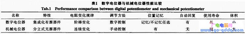
Digital potentiometers represent a promising new type of device. Compared to mechanical potentiometers, they offer numerous advantages, as shown in Table 1, making them suitable replacements in many areas. Any field that involves resistor-based parameter adjustment, calibration, or control can benefit from using a digital potentiometer to create a programmable analog circuit. Additional features include:
1) A type of digital-analog mixed-signal product, it functions as a special form of DAC (Digital-to-Analog Converter), consisting of digital control circuits, memory, and RDAC circuits. The RDAC is a key component, composed of a resistor-based DAC circuit.
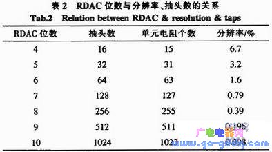
2) Its resolution depends on the number of internal RDAC bits (see Table 2). More bits result in higher resolution.
3) It has a built-in control interface, memory, and resistance system, along with non-volatile EEPROM that allows users to read and write data, programming resistance values through a software interface.
4) It enables digital control and adjustment of resistance, voltage, or current in analog circuits.
5) Multiple digital potentiometers can be connected in serial, parallel, or hybrid configurations.
6) Due to manufacturing variations, the total resistance may have a deviation of 15% to 30%.
7) Low voltage, low power consumption, ultra-small size, and a wide operating temperature range.
1.2 Main Parameters
1) The difference between the highest power supply voltage and the lowest operating voltage, usually ranging from 2.5 V to 5.5 V.
2) The terminal voltage applied to the high-side and low-side voltages, typically between 0 V and VCC.
3) The ratio of the minimum resistance value that can be resolved to the total resistance, expressed as a percentage.
4) The number of taps determines how many terminals the resistor can adjust. For example, if it’s n-bit, the number of taps is 2^n.
5) Nominal resistance tolerance refers to the percentage deviation of the actual resistance from the ideal value.
6) Sliding terminal resistance refers to the on-resistance of the internal analog switch, which varies depending on the internal circuit structure and terminal voltage.
7) Bandwidth, which indicates the frequency response range. Common representations include -3 dB bandwidth, unity gain bandwidth, and gain bandwidth product.
8) Interface refers to the circuit used to connect to a microprocessor or microcontroller.
9) Settling time is the time required for the digital potentiometer to stabilize after a control code change, typically a few microseconds.
10) Resistive noise voltage is the random noise generated by the internal resistance within a certain frequency bandwidth, measured in μV/Hz.
This website aims to support small and medium-sized enterprises with advertising services, offering affordable and effective solutions. We recommend maintenance points and products tailored to your needs. Contact us via QQ or email for more information!
Why do you want to do online advertising?
|
- 0
- like
| Try to find the information you want to see. Inverter sensor patch three no weight loss camera LCD monitor does not boot digital camera XC9237 projector switching power supply laptop processor IPSUSB skills entrepreneurial black screen water heater can not boot circuit design silent transformer XC6102 without sound XC6112 display regulator no image microwave player successful silent GPS tea no picture XC6222 health XC6372 relay filter ML6209 switch washing machine digital camera description remote control without grating 555 protection circuit cancer self-closing Linux charger mobile phone shutdown noise inverter oscilloscope robot Windows antenna indicator light is not bright fiber life transformer stomach market alarm Hard disk watch embedded system woman maintenance process memory XC9236 converter router interview server kidney RFIDLED driver Konka CDMA instrument Panasonic CCD flashing engine multimeter Apple liver motor resistance keyboard integrated circuit current transformer triode governor power supply LED |

Servo Electric Cylinder,Linear Actuator With Speed Control,Parallel Drive Linear Actuators,Long Stroke Electric Linear Actuator
Suzhou Johnson Automation Technology Co., Ltd. , https://www.cn-johnson.com