Conductive polymers exhibit unique electrical properties that can be tailored through doping, allowing for precise control of their resistivity. Accurate measurement of this property is essential for understanding and optimizing the performance of such materials. In the semiconductor industry, the four-probe method is widely used to measure the resistivity of inorganic semiconductors. However, conductive polymers are organic semiconductors with distinct conduction mechanisms and a broad resistivity range (from 10-3 to 1010 Ω·cm). As a result, the traditional four-probe method may not be suitable due to its limitations in accuracy and adaptability across such a wide range.
Current methods for measuring high-resistivity samples often rely on national standards like GB3048.3-83. While effective, these approaches require specific sample shapes and involve complex circuit setups. Additionally, controlling the excitation voltage is challenging—too low a voltage may reduce measurement accuracy, while too high a voltage could damage the sample or introduce unwanted effects. To address these issues and ensure safe, accurate measurements over a wide resistivity range, improvements have been made to the measurement system.
1 Measurement Principle 1.1 Four-Probe Resistance Measurement MethodThe four-probe technique minimizes the impact of contact and wire resistance by using a constant voltage source instead of a constant current. As shown in Figure 1, the voltage applied between probes 1 and 4 is Vs, and the current flowing through the sample is determined indirectly.

Current through the sample:
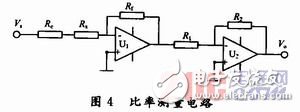
Where: Rw is the wire resistance, Rct is the contact resistance at probes 1 and 4, and R14 is the sample resistance. To determine the sample current I, the total resistance Rx must be calculated. A ratio measurement approach is used here, as illustrated in Figure 2.
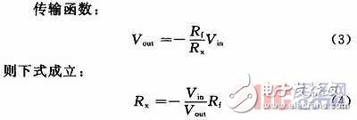
Here, Vin is the input reference voltage, Vout is the output from the amplifier, and Rf is the feedback resistor. This setup allows for more precise and stable measurements under varying conditions.
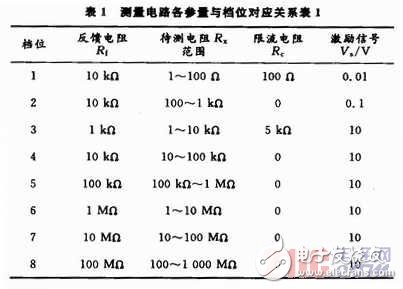
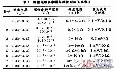
1.2 Measurement ResolutionThe theoretical resolution of the resistance measurement decreases as the resistivity of the sample increases. To maintain high resolution across the entire range, two strategies are employed: (1) increasing Rf for larger resistances, and (2) adjusting the excitation voltage. By using program-controlled amplification technology, different gear positions are designed based on the expected resistance range, with corresponding excitation voltages selected for each. The relationship between gear position and voltage is summarized in Table 1.
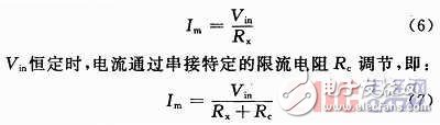
1.3 Current LimitationWhen measuring the resistivity of semiconductor materials, the current through the sample must be carefully controlled. The current should be sufficient to produce measurable voltage differences between inner probes but not so large as to cause thermal effects or alter the material’s properties. For high-resistivity samples, reducing the injection current helps minimize the influence of minority carriers. While the current affects the measured resistivity value, it typically does not change the overall resistivity range. Safe operating currents are derived from this range.
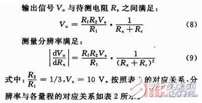
The current through the test sample in this method is given by the following equation:
The system uses an LPC2148 ARM7 microcontroller as the core unit for processing and control. The overall system structure is illustrated in Figure 3.
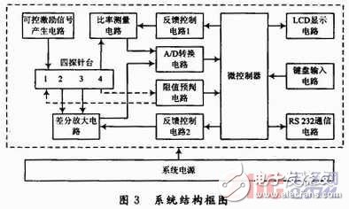
The control processing unit includes an LCD display, a keyboard input interface, serial communication circuits, and two feedback control circuits. A preset current-limiting resistor Rc is used to define the current for low-resistivity samples, and the current can be calculated using Equation (9). The system ensures that the measurement current remains below 2 mA across the full range. The parameters and gear positions are listed in Table 1.
This unit consists of a controllable constant voltage generator, a differential amplifier, a ratio measurement circuit, and an analog-to-digital converter. ADR01 is used to generate a 10 V reference voltage, which is then scaled down to 0.1 V and 0.01 V. The voltage between the inner probes is measured using an AD620 differential amplifier and a high-precision op-amp, AD546. Feedback control circuit 2 adjusts the gain resistor RG to fine-tune the output signal. The ADC, AD7705, provides 16-bit resolution with a sensitivity of 52 μV/LSB when using a 3.401 V reference. The design is shown in Figures 4, 5, and 6.
ZGAR FIT
ZGAR electronic cigarette uses high-tech R&D, food grade disposable pod device and high-quality raw material. All package designs are Original IP. Our designer team is from Hong Kong. We have very high requirements for product quality, flavors taste and packaging design. The E-liquid is imported, materials are food grade, and assembly plant is medical-grade dust-free workshops.
From production to packaging, the whole system of tracking, efficient and orderly process, achieving daily efficient output. We pay attention to the details of each process control. The first class dust-free production workshop has passed the GMP food and drug production standard certification, ensuring quality and safety. We choose the products with a traceability system, which can not only effectively track and trace all kinds of data, but also ensure good product quality.
We offer best price, high quality Vape Device, E-Cigarette Vape Pen, Disposable Device Vape,Vape Pen Atomizer, Electronic cigarette to all over the world.
Much Better Vaping Experience!


ZGAR FIT E-Cigarette Vape Pen,ZGAR FIT Device Vape,ZGAR FIT Vape Pen Atomizer,ZGAR FIT Disposable E-Cigarette OEM vape pen,ZGAR FIT electronic cigarette
Zgar International (M) SDN BHD , https://www.zgarvape.com