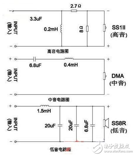
As shown in the figure below is a simple crossover circuit diagram. The low-pass filter composed of L1 and C1 selects the crossover point of 200-54 at 1.5 kHz. Here, the crossover point is appropriately increased, mainly because the cell characteristics are good, and more importantly, the power of the audio is mostly concentrated. Low frequency, appropriate increase of the cut-off frequency of the low-frequency unit, you can give full play to the unit's special features, the sound will be more full and powerful. If the crossover point is too low, not only will the unit advantage be lost, but the burden of the intermediate frequency unit will be increased, causing the amplitude overload and the increase of distortion.
Although the effective frequency response of the intermediate frequency unit is as wide as 800 Hz to 10 kHz, the bandpass filter composed of L2, L3 and C2 and C3 only takes a frequency band of 1.5 to 6 kHz, which is also its golden band. The high-pass filter composed of L4 and C4 sets the frequency division point of YDQG5-14 to 6 kHz, and the lower limit cutoff frequency of this unit is also higher, which makes it easier to use its features in the high frequency band. Due to the reasonable selection of the crossover point, each of the three units operates in the band with the highest acoustic efficiency, so the overall sensitivity of the system is also 1~2dB higher than the average characteristic sensitivity of each unit.
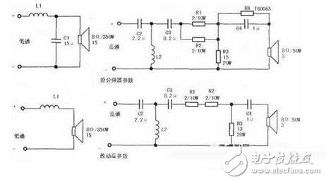
The frequency divider component is small, and the circuit is also very simple. The minimum requirement for the frequency divider capacitor is that the high frequency characteristic is good, and the loss and capacity error are small. The current polypropylene CBB non-polar capacitors have a loss tangent value of only 0.08% to 0.1%, excellent high frequency performance, small size, no sense, and low cost, and are fully capable of the Hi-Fi system frequency dividing circuit. This speaker uses CBB21 and CBB22 capacitors with a withstand voltage of 63V, and 4.7 uF with two 4.7 uF parallels.


The speaker splitter is a combined filter that can distinguish the sound signals of different frequency bands, respectively give amplification, and then send them to the speakers of the corresponding frequency band for playback, so that the playback characteristics of each frequency are more balanced. .
The role of the speaker crossoverThe function of the crossover is equivalent to the "brain" in the speaker. The crossover plays a vital role in the sound quality. The frequency divider can be used to send the high frequency signal to the tweeter, and the low frequency signal is sent to the woofer, so that the high and low frequency signals can be used in different ways, and the working frequency band advantages of the respective speakers can be utilized as much as possible to ensure the speakers of different working frequency bands. Give full play to make the playback characteristics of each frequency more balanced. So it is not difficult to see that a well-designed crossover can better play out the characteristics of the unit to make the sound play better quality.
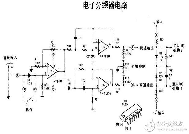
Circuit diagram of speaker divider
From the working principle, the frequency divider is a filter network composed of a capacitor and an inductor. The treble channel only allows the high-frequency signal to pass through and blocks the low-frequency signal; the bass channel is just the opposite, only the bass passes and blocks the high-frequency signal; the mid-range channel is a band-pass filter, except for one low-high one-divide point The frequency between them can pass, and both the high frequency component and the low frequency component will be blocked.
The speaker crossover uses the internal filter components to dispose of the music signal output by the amplifier, so that the signals of specific frequencies of each unit pass. The speaker crossover circuit diagram can clearly show how to effectively use the different characteristics of the speaker unit, and optimize the combination to make each unit develop its strengths and avoid weaknesses, and fully exert their potential.
In the speaker crossover circuit diagram design process, if you need to balance the difference between the high and low woofer flexibility, you can also participate in the attenuation resistor; if you need the speaker's impedance curve to be psychologically flat, you can also increase the impedance of the resistor and capacitor. Compensation network.
Speaker three-way crossover circuit diagramThe crossover is the "brain" in the speaker, which is very important for the sound quality. The music signal output by the power amplifier must be processed by the filter wave component in the frequency divider to allow the signals of specific frequencies of each unit to pass. It is necessary to scientifically design, rationally and rigorously design the frequency divider of the speaker to effectively modify the different characteristics of the speaker unit, optimize the combination, so that each unit can develop its strengths and avoid weaknesses, and exert its potential as much as possible to make the frequency response of each frequency band change. Smooth, accurate phase of the sound image, in order to make the music played by high, medium and low sounds clear, co-ordinated, clear, comfortable, wide and natural sound quality.
The speaker divider is a combined filter that splits the sound signal into frequency bands. The audio two-way divider consists of a high-pass filter and a low-pass filter, while the three-way crossover adds a band-pass filter. This article describes a simple speaker three-way crossover circuit diagram, the input can be connected to the same output. as the picture shows.
SMT Motor
SMT Motor, original and new ,in stock, quality gaurantee.
SMT motor : actuator motor,servo motor, converyor motor,rail motor, bom stepping motor, rizing motor, Z camera motor, Y camera motor, X camera motor.
Smt Motors
Smt Juki Motors
Original Smt Servo Motor
Original Smt Motors
Holder For Smt Type
Smt Battery Holder
SMT Holder
Battery Holder
Filter For Smt Machine
High Quality Smt Filter
Smt Filter
Smt Machine Filter
Smt Tape Feeder Parts
Feeder Parts For Smt Machine
Smt Machine Spare Parts
Original SMT Feeder
Original SMT Cable
Smt Machine Cable
Smt Spare Parts Fuji Cable
Smt Cable
SMT Belt
Smt Siemens Belt
Smt Juki Belt
Smt Conveyor Belt
Smt Camera
Smt Laser
Camera For Smt
Smt Siemens Camera
Smt Parts Plastic Rail
Smt Plastic Rail
Smt Juki Plastic Rail
Juki Plastic Rail
SMT Nozzle For Yamaha
Yamaha Nozzle
Nozzles For Yamaha Machine
Smt Yamaha Nozzle
Smt SIEMENS Nozzle
Nozzles For Siemens Machine
Smt Nozzle For Siemens
Siemens Nozzle
Smt Nozzle For Samsung
Nozzles For Samsung Machine
Smt Samsung Nozzle
Panasonic Nozzle
Smt Panasonic Nozzle
Smt Nozzle For Panasonics
Nozzles For Panasonic Machine
Smt Juki Nozzle
Nozzles For Juki Machine
Juki Nozzle
High Pressure Juki Nozzle
I-Pulse Nozzle
High Pressure I-pulse Nozzle
Nozzles For I-pulsemachine
Smt I-pulse Nozzle
High Pressure FUJI Nozzle
Nozzles For Fuji Machine
Fuji Nozzle
Smt Fuji Nozzle
Smt Nozzle
Smt Parts Nozzle
Smt Nozzle For Machine
Smt Spare Parts Nozzle
Yamaha Smt Feeder
YAMAHA Feeder
Smt Machineyamahafeeder
Smt Feeder For Yamaha
Smt Feeder For Siemens
Smt Machine SIEMENS Feeder
Siemens Smt Feeder
Siemens Feeder
Samsung Smt Feeder
Smt Machine SAMSUNG Feeder
Samsung Feeder
Smt Feeder For Samsung
Panasonic Smt Feeder
Panasonic Feeder
Smt Machine Panasonic Feeder
Smt Feeder For Panasonic
Smt Feeder For Juki
JUKI Feeder
Juki Smt Feeder
Smt Machine Juki Feeder
I-Pulse Feeder
Smt I-pulse Feeder
Smt Parts I-pulse Feeder
I-pulse Type Feeder
Pneumatic Feeder
FUJI Feeder
Smt Fuji Feeder
Fuji Smt Tape Feeder
Smt Machine Feeder
Smt Tape Feeder
Smt Feeder
Feeder For Smt Machine
Siemens Control Valves
Smt Siemens Valve
Siemens Vacuum Valve
Siemens Valves
Smt SAMSUNG Valve
Samsung Vacuum Valve
Samsung Control Valves
Samsung Valve
Juki Vacuum Valve
Juki Ejector
Juki Vacuum Ejector
Juki Valve
Smt Motors,Original Smt Motors,Smt Juki Motors,Original Smt Servo Motor
Shenzhen Srisung Technology Co.,Limited , https://www.sr-smts.com