PT2262 / PT2272 is a low-power and low-cost general-purpose codec circuit in CMOS process. Due to its strong anti-interference ability, low power consumption, few external components, and wide operating voltage range, it is widely used in vehicle anti-theft systems. , Home anti-theft system, remote control of toys and other electrical appliances.
Because PT2262 / PT2272 requires pairing, that is, only when a pair of codec chip address settings are completely the same, can the information be received to realize remote control. Therefore, it is usually used in one-to-one unidirectional control. It is difficult to achieve one-to-many control and two-way information transfer. Even the use of software decoding is mostly to achieve one-way control. Here, a multi-function control system for one-to-many bidirectional information transmission based on the universal chip PT2262 / PT2272 is designed.
1. System Structure
The system consists of a control center and multiple terminals, each terminal is equipped with a pair of codecs with the same address. Different terminals are distinguished by different addresses. Each terminal can accept instructions sent by the control center, and can also upload the terminal status to the control center. The system structure is shown in Figure 1. The control center can set the corresponding control keyboard, display output or control center computer as needed. The connection medium between each terminal and the control center can be selected according to the specific situation, such as wireless remote control or via telephone lines, cable TV cables, power lines, etc. It's just that different media choose different modulation carriers.
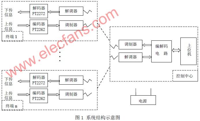
The codec chip of each terminal is manually set with the same set of addresses. The upload information encoded by PT2262 is modulated and sent to the control center, where the address information is used by the center to distinguish the attributes of the terminal; the control signal with address information sent by the control center is demodulated and sent to the PT2272 for decoding. After the address code is checked twice, only the same information as the set address can be decoded and output to realize the corresponding control function.
2. Data structure of PT2262 / 2272 chip
The PT2262 encoder can compile data and addresses into code waveforms. It can have up to 12-bit tri-state address terminal pins (floating, connected to high level and low level), any combination can provide 531441 address codes, PT2262 up to There can be 6-bit data terminal pins, and the set address code and data code are serially output from 17-pin. PT2272 is a decoder paired with PT2262 and also has a 12-bit three-state address.
The encoded data of the encoding chip PT2262 is sent out in units of word codes, and each word code is composed of a 12-bit address (or data) code and a synchronization signal SYNC. Similarly, the decoding chip PT2272 is also received in word units, and the synchronization signal is used as the reception start mark.
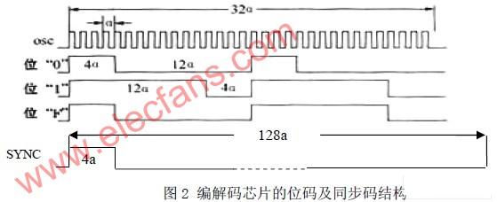
Figure 2 shows the bit code structure of the PT2262 / 2272 chip. It can be seen that it takes 32 basic clock cycles a to send or receive an address (or data) code, and different code words are distinguished by different configurations of signal levels during this period. If the unit is 4 basic clock cycles (4a). The code of the bit code "0" is "10001000", the code of the bit code "1" is "11101110", and the code of the bit code "F" is "10001110".
In the figure, SYNC is a synchronization bit signal. A synchronization bit signal occupies 128 basic clock cycles, which is equivalent to the width of four address codes.
The sync bit signal is both the start mark of a word code and the dividing line of adjacent words.
3. The control center codec module is designed in EDA mode. The block diagram of the circuit structure is shown in Figure 3. The module integrates encoding and decoding, and automatically sets the three states corresponding to the 8-bit addresses A0-A7 of PT2672 / PT2272 to perform automatic address encoding of the control center.
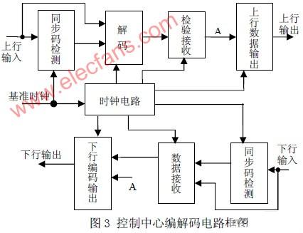
The upstream input signal comes from the demodulator of the control center (the modulation signal generated by each terminal PT2262). This signal is read in by the clock signal bit by bit, and the synchronization code detection is performed by the synchronization code detection circuit. If a synchronization code is detected, the subsequent signal is input To the decoding circuit for decoding (corresponding to the coding rules), the decoded signal is checked and received by the receiving circuit, and the circuit stores the decoded signal for a fixed length. If the same decoding result is received twice in succession, it is considered that there is indeed upstream information (such as Query information response), then send this set of decoded signals to node A in parallel. The signal of point A is sent in two ways. On the one hand, it is output by the upstream data output circuit for corresponding display or sent to the control computer through the serial port. On the other hand, it is sent to the downstream code output circuit to feed back confirmation information to the terminal.
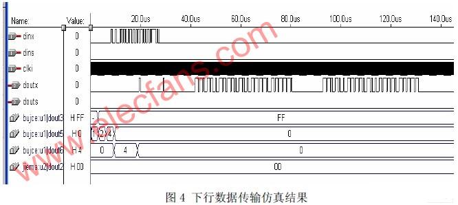
The downstream input signal is generated by the control center. This signal is read in by the clock signal, and the synchronization code is detected by the synchronization code detection circuit. If a synchronization code is detected, the subsequent signal is input to the data receiving circuit, where the serial signal becomes parallel The signal is sent to the downstream code output circuit. The circuit preferentially receives the signal from point A, encodes the received signal, and sends it out in a serial manner. The downstream output signal is modulated by the modulator and sent to each terminal. Figure 4 shows the simulation results of downlink data transmission.
4. Communication method
The information transmission of the control center adopts the way of the flag bit (synchronization code), fixed length transceiver. The communication synchronization code between the control center and each terminal is "PTSN" in the encoded signal transmitted by PT2262.
After detecting the code, the control center starts the subsequent decoding, receiving and other circuit operations; similarly, the downlink signal sent by the control center to the terminal also starts with the same synchronization code.
The valid data from the terminal is 12-bit, 8-bit tri-state address and 4-bit binary data. After decoding, each address code must be represented by at least two binary numbers. For convenience, each data here is also represented by two binary numbers. In this way, the 12-bit valid data is decoded and becomes a set of 24-bit binary code, which is combined with the synchronization code into a 32-bit fixed-length code.
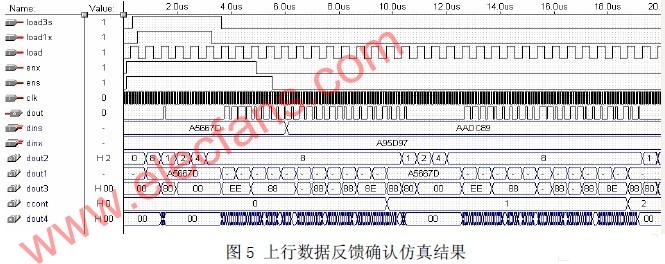
As mentioned above, the decoding result of each address or data is "01", "10" or "11". Under normal operation, the number of "0" s can be up to two digits to ensure that the synchronization code does not overlap with the data code. . After detecting the code, the control center starts the subsequent upstream data reception, decoding and other work. The way the terminal sends out information is to send it repeatedly, and stop after getting confirmation from the control center. Figure 5 shows the uplink data feedback to confirm the simulation results.
5. Conflict resolution mechanism
In order to solve the conflict problem of uploading signals of each terminal, each terminal uses the time-division multiplexing method to transmit information on the same channel. The specific method is that the control center sends instructions to each user in turn according to the address code, and each instruction only responds to the user with the corresponding address code: send a message to the control center such as the terminal's operating status. Each time the center sends a command, it waits for a specific time to receive the corresponding upload information. If no information is received here, it is considered that the terminal is faulty. After a round of commands is issued, the faulty terminal is queried again to confirm its status and react. .
6. Conclusion
The above solution overcomes the limitation of one-to-one matching use of the universal codec chip PT2262 / 2272, and realizes one-to-many two-way communication. It can be applied to point-to-multipoint intelligent control, such as smart home appliance control, medical institution monitoring, etc. The design has been applied in the community surveillance system, and the effect is good.
Brushless Dc Motor,Brushless Dc Electric Motor,Brushless Electric Motor,Bldc Motor With Encoder
Jinan Keya Electron Science And Technology Co., Ltd. , https://www.keyaservo.com