1. Two Conditions for Op-Amp Oscillation
Oscillation in an operational amplifier occurs when two main conditions are met: first, the loop gain must be greater than 1 (|AF| > 1), and second, the phase shift between the input and feedback signals must exceed 180 degrees. This is because negative feedback introduces an additional phase inversion of 180 degrees, making the total phase shift over 360 degrees when combined with the internal phase lag of the op-amp.

The open-loop gain A is defined as the ratio of output voltage to input voltage (A = Xo/Xi), while the feedback factor F is the ratio of feedback voltage to output voltage (F = Xf/Xo).
2. Method to Determine Operational Amplifier Oscillation
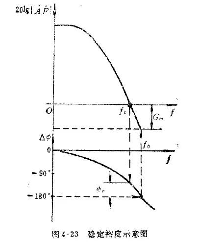
One common method to assess oscillation is by checking the phase margin. When the magnitude of the loop gain |AF| is 0 dB (i.e., 20 log |AF| = 0), the phase shift should be less than 180 degrees. If the phase shift exceeds this value, the system becomes unstable and may start oscillating.
3. Methods to Eliminate Self-Excited Oscillations
To prevent self-oscillation, we can address the problem from two angles: reducing the loop gain or increasing the phase margin.
(1) Reducing Loop Gain
Reducing the loop gain can help stabilize the system, but it also increases the gain error. For an op-amp, decreasing the feedback coefficient F has a similar effect. The higher the F, the more likely the circuit is to oscillate. In resistive feedback circuits, F can be as high as 1, such as in a voltage follower configuration. This is why voltage followers are prone to oscillation, even though their gain error is small. Many op-amp datasheets highlight "unity gain stability" to indicate that they are designed to avoid oscillation at a gain of 1.
Additionally, the ability of a voltage feedback amplifier (VFA) to drive capacitive loads increases with closed-loop gain. For example, if the closed-loop gain is 1, the VFA can drive up to 100 pF; if the gain is 10, it can handle 1000 pF. However, since closed-loop gain is often fixed during design, this method has limited practical use.
(2) Increasing Phase Margin
Phase compensation techniques are commonly used to improve stability. These include lag compensation, lead compensation, and lag-lead compensation.
Lag compensation introduces a phase lag, which reduces the dominant pole frequency and narrows the bandwidth—similar to an RC low-pass filter.
Lead compensation, on the other hand, introduces a phase advance, which widens the frequency response—like an RC high-pass filter.
For capacitive loads (CL), the loop gain decreases due to the interaction between the output resistance and the load capacitance. At this point, phase lag becomes the critical factor rather than the gain.
1. Open-Loop Compensation – Lead Compensation
For small capacitive loads (<1500 pF) or when the load impedance is known, a resistor RX can be placed in series between the op-amp output and the load capacitor. Typically, RX ranges from 10 to 100 ohms.


2. Closed-Loop Compensation – Lead Compensation
For larger capacitive loads (>1500 pF) or when the load impedance is uncertain, a resistor RX can be placed inside the feedback loop, and a capacitor CF can be connected in parallel with the feedback resistor. This helps cancel out the poles caused by input and stray capacitance. Typically, RX is 50–200 Ω, and CF is around 3–10 pF.

Silicone rubble cold shrinkable tube
Dongguan Zhonghe Electronics Co., Ltd. , https://www.zhonghesleeving.com