1. Two Conditions for Op-Amp Oscillation
Oscillation in an operational amplifier occurs when two key conditions are met:
1. The loop gain must be greater than 1 (|AF| > 1). This means that the signal is amplified enough to sustain oscillation.
2. The phase difference between the input and feedback signals must exceed 360 degrees, with an additional phase shift of at least 180 degrees due to negative feedback. This ensures that the feedback is regenerative rather than stabilizing.

In this context, A represents the open-loop gain (A = Xo/Xi), and F is the feedback factor (F = Xf/Xo).
2. Method for Judging Operational Amplifier Oscillation
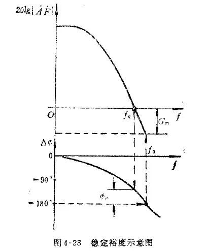
One common approach to assess whether an op-amp might oscillate is by evaluating the phase margin. Phase margin is defined as the difference between the actual phase shift and 180 degrees at the frequency where the loop gain is 0 dB (i.e., 20log|AF| = 0). If the phase shift exceeds 180 degrees at this point, the system becomes unstable and may oscillate.
3. Methods to Eliminate Self-Excited Oscillations
To prevent self-oscillation, we can address the two main causes: excessive loop gain and poor phase margin.
(1) Reducing Loop Gain
Lowering the loop gain can help stabilize the system, but it may also increase the gain error of the op-amp. One way to reduce the feedback coefficient F is by adjusting the resistive feedback network. For example, in a voltage follower configuration, F is 1, which makes the circuit more prone to oscillation. This is why some op-amps are specifically designed for unity-gain stability.
Additionally, the ability of a voltage feedback amplifier to drive capacitive loads increases with closed-loop gain. For instance, an op-amp operating at a closed-loop gain of 1 can drive up to 100 pF, while at a gain of 10, it can handle 1000 pF. However, since the closed-loop gain is often fixed in a design, this method has limited practical application.
(2) Increasing Phase Margin
Phase compensation techniques are widely used to improve stability. These include lag compensation, lead compensation, and lag-lead compensation.
Lag compensation introduces a phase lag, which reduces the main pole frequency and narrows the bandwidth—similar to an RC low-pass filter.
Lead compensation introduces a phase lead, which widens the bandwidth by adding a zero to the amplitude response—similar to an RC high-pass filter.
For capacitive loads (CL), the loop gain decreases due to the output resistance and CL. As a result, the phase lag becomes the dominant factor in determining stability.
1. Out-of-Loop Compensation – Lead Compensation
This method is suitable for small capacitive loads (<1500 pF) or when the load impedance is known. A resistor RX (typically 10–100 Ω) is placed in series between the op-amp output and the load capacitor.


2. In-Loop Compensation – Lead Compensation
This technique is ideal for larger capacitive loads (>1500 pF) or when the load impedance is uncertain. A resistor RX (50–200 Ω) is placed inside the feedback loop, and a capacitor CF (about 3–10 pF) is connected in parallel with the feedback resistor. This helps to cancel out parasitic capacitances and improve stability.

corrugated aluminium foil, aluminum foil corrugated conduit tube, aluminum foil corrugated conduit heat tube, aluminum foil corrugated conduit
Dongguan Zhonghe Electronics Co., Ltd. , https://www.zhonghesleeving.com