[Introduction] The automotive environment poses a huge challenge for LEDs. LEDs must provide stable light output. Even if the electrical conditions and heat dissipation conditions around the headlights change constantly, the flux and color point of the lights must remain constant. This paper proposes a fully integrated and flexible automotive LED driver design that not only meets the various requirements of automotive exterior lighting applications, but also overcomes many of the shortcomings of existing electronic device design...
This article refers to the address: http://
LED lamps are increasingly used in these automotive front lighting applications, mainly because of their unique advantages in style and design compared to conventional incandescent or high-intensity discharge (HID) lamps, and more recently It is thanks to the low power consumption feature. However, it is equally important that with the continuous development of LED technology, higher power levels and wider color gamuts can be provided. At present, in the front lighting application of automobiles, the performance of LED lamps is no less than that of incandescent lamps.
This article aims to explore this important component of LED lighting systems and points out the factors that need to be considered when developing LED external light drive electronics architectures. The article will explain the reasons for using LED lights in automotive exterior lighting applications (such as long life and low power consumption) and discuss the challenges of introducing LED lights in these applications, including industry requirements (AEC-Q100) and features. Claim.
On this basis, we will delve into the impact of these applications on electronic devices in order to fully exploit the huge potential of LED lights. We will present a general-purpose LED lighting system architecture that also lists the features required for electronic control devices. These features include LED thermal management, flexible drive of different LED configurations, and cost-effective system design.
LED challenges in automotive applications
The automotive environment poses a huge challenge for LEDs. LEDs must provide a stable light output. Even if the electrical conditions and thermal conditions around the headlights change, the flux and color point of the light must remain constant.
Since the light output of the LED is proportional to the current applied to the LED, and the LED uses a diffusion-type production process, even in the same batch of products, the light output may be different under the same driving current. In order to avoid this unfavorable difference, LEDs (also called "screening") are often selected based on certain parameters (such as forward voltage, flux output). Filtering ensures that the same batch of LEDs is more consistent in terms of light output and color point.
The LED must also ensure that the light output meets the minimum legal flux requirements for the specific application over the ambient temperature range of -40 ° C to +125 ° C. The headlamps require a luminous flux of around 1,000 lumens and provide the minimum required light output over the operating temperature range.
In order to achieve this luminous flux requirement, several LEDs may be connected in series or in parallel. Bringing together a number of high-brightness LED lights together places high demands on thermal management, as the LED's light output drops dramatically as the LED temperature increases, and the color point shifts. Therefore, the heat emitted by the LED during the generation of this order of light must be conducted out through the heat sink. In some extreme cases, it may be necessary to reduce the LED drive current to avoid overheating and damage to the LED.
The automotive industry also imposes stringent requirements on the reliability of LEDs. LED solutions must be able to meet the stringent requirements of the AEC-Q100 standard. This means that LEDs and driver electronics must pass the standard certification.
In addition, automotive manufacturers and suppliers of primary lighting products have proposed other functional requirements, such as the use of LEDs to provide dual functions. For example, daytime running lights sometimes act as stop lights, and taillights are sometimes used as stop lights. This means that the light provided by the LED must have two output levels that can be controlled. To avoid color point shifts at different current levels, most system designs reduce the average current of the LED by performing a pulse width modulation (PWM) process on the LED current while maintaining a constant peak current. This allows for a lower light output level at the same color point. The next section will explain why LEDs are used in automotive lighting in automotive applications.
Why use LEDs in automotive lighting?
For car manufacturers, the advantages of style are still one of the main reasons for using LED lights. Clearly, automakers see opportunities to further consolidate their car brands. A variety of lighting designs have benefited from the greater design freedom offered by LED lights. The more famous early examples include the Audi A8/A6.
However, the focus is shifting to other advantages that LED lights bring to automotive lighting applications. These include lower power consumption, longer life and faster start-up times.
The University of Michigan School of Transportation Research (UMTRI) released a report in 2008 that evaluated the energy consumption of conventional incandescent and LED solutions for daytime lighting. They found that for equivalent functions, the LED solution consumes 50% less energy (23W vs. 46W). This savings translates directly into fuel efficiency while reducing passenger car CO2 emissions by 50%.
This fuel efficiency is important for automakers preparing to develop all-electric vehicles. For consumers, an important purchase standard is the distance that an electric car can travel when it is fully charged. To this end, automakers are looking for ways to improve the energy consumption of various functions and thus improve the car's endurance. LED lights clearly have great energy-saving advantages and are increasingly becoming a natural choice for lighting design engineers.
Another important factor contributing to the inefficiency of LED efficiency and LED penetration in automotive lighting applications is the LED's illumination efficiency, which is lumens per watt (lm/W). This indicator measures the amount of light output per watt of energy consumed by an LED lamp. The higher the value, the higher the efficiency with which the LED converts input power to light output. Today's high-brightness LED lights can achieve 100-150lm/W illumination efficiency, while a 60W incandescent lamp is only 10-18lm/W.
The improvement of this indicator has greatly expanded the application range of LED lamps and expanded into the front lighting system of the car based entirely on LED lights. In particular, LED-based headlights include features such as high beam and low beam adjustment.
LED impact on electronic system architecture
In fact, the many functions and advantages of LEDs depend on the electronics used to drive them. Electronic drive solutions have a huge impact on the efficiency and performance of LEDs and the entire system.
Figure 1 shows a general-purpose LED lighting system architecture for external LED lights. The figure shows the main components of a general lighting control module (LCM) for driving LEDs. Although some of the architecture's LEDs are on the same module as the driver electronics, the LEDs of this solution are located on a separate LED module of the driver control module.
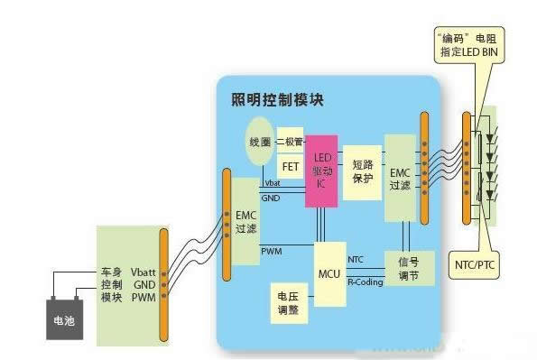
Figure 1: A general-purpose automotive LED lighting system architecture
As mentioned earlier, LEDs for automotive exterior lighting applications typically require some form of thermal management. To this end, the program has a temperature sensor near the LED. The sensor is monitored by the LCM. If the LED temperature rises, the control module will reduce the current entering the LED, thereby preventing the LED from overheating and preventing it from malfunctioning.
In order to identify the batch of LEDs, a filter resistor or code resistor is typically used. By measuring the value of this resistor, the LCM can determine the exact amount of current that should be supplied to the LED to ensure that the specific function of the light output is achieved.
The LCM receives power and control signals from the body control module. These often include batteries and ground power for power. Some architectures contain a control line from the body control module that changes the function of the LED string through the control signals. For example, when using the same LED string to act as a daytime running light and a stop light, a control signal is needed to select the desired function. A more advanced architecture uses a CAN network to control the lighting, so a CAN bus cable is used to determine the specific function.
In order to process these control signals from LED modules and body controllers, LCMs sometimes use a microcontroller. The microcontroller can read these control signals and configure the driver IC accordingly. This helps increase the flexibility of the LCM to drive any LED configuration, thereby increasing the reusability of the drive control board in different automotive platforms.
The main function of the driver circuit itself is to provide controlled current to the LED string. The circuit can be implemented in different architectures such as linear regulators or switching regulators. However, as power levels increase, efficiency becomes more and more important, and switching regulators are often employed. These converters can be in boost, buck, or buck/boost topologies. Each topology has its own strengths and weaknesses, depending on output flexibility, efficiency, and system cost, depending on the specific design.
When deciding which topology to use, the following facts must be considered: the supply voltage supplied by the battery to the LCM varies widely, down to 6V (the cold start of the modern start-stop engine), up to 24V. As most automakers insist, under these conditions, the external lighting function should function properly, so the driver circuit must be able to provide the corresponding output voltage/current to the LED string over such a wide input voltage range to drive the LED. . Under these requirements, a buck/boost topology is often used.
In addition, as the lighting control module continues to evolve toward general-purpose models, the buck/boost converter topology is the primary choice because it provides maximum flexibility in output voltage and is immune to input voltages. Small differences in efficiency between different topologies.
As mentioned earlier, the LCM provides PWM current to the LEDs. However, in order to avoid the PWM current causing the visible light flicker of the LED light, a PWM frequency of 200 Hz or more is generally employed. The PWM duty cycle can also be varied to provide different average currents to the LED string depending on the desired function, such as daytime running lights or stop lights.
It can be seen that the lighting control module must be able to convert the input power from the body controller into a PWM current with a frequency exceeding 200 Hz and a corresponding duty cycle to provide the appropriate average current to the LEDs to achieve the desired function.
The use of a DC/DC switching regulator topology also requires ensuring that the control module is not radiated and immune to electromagnetic interference. Therefore, proper electronics design and board layout are required to avoid this interference.
In the schematic of Figure 1, the LEDs are independent of the driver control module and are connected by a connector. This architecture requires protection of the LED from accidental shorting of its battery or ground pins due to connector failure, thereby avoiding damage to the LED and driver circuitry.
In addition to short-circuit conditions, LCMs also need to be able to detect LED faults. This includes detecting open and short circuits of the LED. When an individual LED in an LED string has an open circuit fault, it is relatively easy to detect, but the detection of a short circuit fault is more challenging. The inherent diffusivity of a single LED forward voltage becomes very noticeable as it accumulates in longer LED strings. This increases the difficulty of detecting when a short circuit occurs. When the LCM detects a fault LED, it may be necessary to send a diagnostic signal back to the body control module to alert the driver.
This requires the use of a lighting control module to provide all of the above functions while meeting the stringent requirements of the automotive industry standards. This means that the module and related components must pass the AEC-Q100 compliant car certification. Automotive lighting is considered to be an important function related to safety, so its reliability is a top priority.
LED driver design solutions
As can be seen from the above requirements, the challenge is how to design a solution that delivers the required functionality, flexibility, system reliability and integration while reducing system cost.
One possible solution is to use the ASL1010PTK driver IC from NXP Semiconductors. The ASL1010PTK driver IC integrates the core functionality required for automotive LED lights and is a compact, all-in-one solution with no additional components. For the LED module design, it is beneficial to reduce costs, enhance aesthetics and improve reliability.
In addition, this system solution is extremely flexible, independent of automotive platform and LED configurations, and eliminates the need to redesign PCB boards. The integrated design eliminates the redundancy of different platforms and the need for external microcontrollers, keeping system costs low.
The ASL1010PTK driver IC uses a buck/boost topology to safely drive up to 20 LEDs with standard automotive battery voltage. The output voltage is extremely flexible, ranging from 6V to 60V, supporting all types of LEDs currently on the market. Drive high-brightness LEDs in automotive applications.
The schematic in Figure 2 shows a typical reference voltage design for a driver circuit.
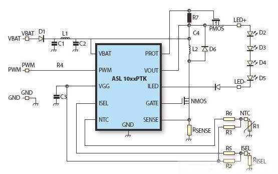
Figure 2: Schematic diagram of a typical application (using the ASL1010PTK for automotive front lighting).
The ASL1010PTK driver IC is based on the ABCD9 technology node (this is NXP's automotive technology platform that drives analog mixed-signal integration). In this way, the driver can operate from a supply voltage of 6V to 60V to meet the start and stop conditions and the transient voltage requirements of the ISO7637 standard.
Due to the high level of integration of the driver ICs, the application design maintains system flexibility while requiring very few external components. In the application diagram shown in Figure 2, the temperature feedback function is implemented by a small number of components, which can control the temperature and performance of the LED; the fault detection function can provide feedback when the LED fails; the short-circuit protection function enables the LED and the driver IC Protected from battery and ground pin shorts; flexible current selection and PWM programming; adjustable LED internal PWM generation, allowing the same LED to be used as both daytime and stop lights. LED undervoltage and overvoltage protection.
With this small, thermally-dissipating device (HVSON14), the driver IC can deliver up to 1A of current to the LED string. Thanks to the high-precision integrated current source, the driver IC eliminates any LED ripple current and eliminates the need for additional external components.
Summary of this article
In recent years, the application of LEDs in the automotive field has grown substantially, due to the unparalleled design flexibility, longer life and lower power consumption of LEDs. The performance of the LED itself has also been greatly improved, increasing its usability in automotive applications.
As LED applications continue to grow, we need a more efficient, robust, and cost-effective electronics and driver IC to make the benefits of LEDs even better in automotive applications.
Based on a general-purpose LED lighting system architecture, we explored the features required for electronic control devices, including LED thermal management, flexibility to drive different LED configurations, and cost-effective system design.
To meet these different requirements, we have proposed a fully integrated and very flexible automotive LED driver IC solution. The ASL1010PTK provides great convenience in circuit design, minimizing the number of external components, while providing the necessary functions to drive automotive LEDs and maintaining greater flexibility at the system level.
- Perfect for all vehicles that use a standard US EU license plate,the angle of camera can be adjusted 45 degrees by loose screw.
- [Equipped with 4 6 8 Night Vision Infrared LEDs optional]extends visibility in low light condition, ensuring complete safety even at full darkness.
- [100% Waterproof & Low power consumption]Waterproof IP68 Rating and Consume less than 40 mA.Ensure it have a long time service life.
- [ The total length of the wire is 32 ft] It is perfect for most cars and SUV RV PICKUP,Easy to install
-
[Reliable & Friendly Customer Service] Ready to respond within a 24 hour time frame. 30-Day Money Back Guarantee, 12 Month Replacement Warranty and Lifetime Support Guarantee

License Plate Reverse Camera,License Frame Backup Camera,Wired License Frame Backup Camera,Led License Frame Backup Camera
Shenzhen Sunveytech Co.,LTD , https://www.sunveytech.com