When measuring the picosecond rise time of a gallium nitride (GaN) transistor, even a 1 GHz observer and a 1 GHz probe may not be sufficient. Accurately determining the rise and fall times of GaN transistors requires careful attention to your measurement setup and equipment. Let's take a look at some of the best practices for using TI's recently introduced LMG5200 integrated half-bridge GaN power module for accurate measurements.
Before ordering the LMG5200 Evaluation Module (EVM), please confirm that your bench equipment accurately measures the wide band gap (WBG) based on GaN (US Department of Energy considers "basic" technology to better utilize our energy resources) Semiconductor products such as the LMG5200. If your device looks like the one shown here, you may need to upgrade your scope and probe.
Measuring the voltage conversion of a WBG semiconductor requires a device with a sufficient measurement bandwidth. The oscilloscope's bandwidth is characterized by a -3dB frequency at which the amplitude of the sine wave (shown on the oscilloscope) has dropped to 1/√2 or 0.707 of the input signal. In general, if the bandwidth of the input signal is equal to the bandwidth of the observation instrument, then the oscilloscope will have an amplitude attenuation error of 30%. If you are using a digital storage oscilloscope (DSO), the sampling rate imposes additional restrictions. For example, when all four channels are occupied and the Nyquist sampling theorem requirements apply, a four-channel, 1Gs/sec DSO usually has only 250Ms/sec capability! As a rule of thumb, if the observer's rated bandwidth is X, the maximum signal frequency that you can actually measure (within 3% error) is X/3. To make the error only 1%, your signal bandwidth should not exceed X/5.
In addition, the oscilloscope probe also increases the measurement error, which can be modeled as a resistor-capacitor (RC) low-pass circuit. What's more, you are not looking at a pure sine wave when measuring switch transitions. What is the effective bandwidth of the rise and fall times of the switch nodes? Mathematically, you can estimate the output of the probe as an applied voltage step, as shown in Equation 1:
Vout = Vin(1-e^t/RC)(1)
The rise time is often expressed as an output transition (10 to 90% of its final value). With Equation 1, the 10% point is 0.1RC at the time and the 90% point is 2.3RC, and since the probe's time constant is 1/2Ï€fRC, the bandwidth expression can be determined.
RC = tr/(t90% - t10%) = tr/2.2RC = 1/2Ï€f (2)
Therefore, the required bandwidth can be calculated by this formula: Bandwidth = 0.35/tr
This relationship allows you to evaluate the equivalent bandwidth of the signal based on the rise time. For example, if you want your GaN device to turn on within 500 ps, ​​you need an observer that can achieve 0.35/500 ps (700 MHz) - and you also need a probe that has at least as much bandwidth. Knowing your probe and scope bandwidth, you can apply a square root (RSS) of the sum to estimate the actual rise time based on the statistical error of the relevant measurement equipment described in this article.
In order to confirm the expected demand, the author evaluated three measurement settings. The first setup has a handheld TekScope with 100MHz/500Ms/sec; the second setup is a 500MHz/2.5Gs/sec DPO4051; the third setup is a 1GHz/5Gs/sec MDO4104-6. After the author's settings, the LMG5200 can convert 24V to 12V at a current of 5A. The switching frequency is set to 1 MHz; a 52% duty cycle is necessary because of the loss of power stage compensation. The power conversion efficiency measured by the author was -96%.
In order to determine the rise time, the author used an observer cursor. If you want to use the observer to calculate the rise time, be sure to set the sample rate to collect a sufficient number of data points. The Nyquist theorem requires at least two or three sampling points, but the author suggests that there should be four or five sampling points on the rising edge. This shows that if the rise time is less than 1 ns, even a 5 Gs/sec sampling capability will still be insignificant.
The probe bandwidth is equally important; even if the author's probe bandwidth is 1 GHz, significant errors can still occur. Note that in some cases, the observing instrument may have more or less than the specified standard, depending on the manufacturer, setting the calibration, and the age of the viewing instrument and probe. According to the test, the author will say that in order to measure WBG switching, the system bandwidth of 1 GHz is the absolute minimum requirement.
So, what did the author find? Using the low-inductance detection technique described in this article, the rise time measured by a 100-MHz observation instrument shown in Figure 1 is 3 ns – this is clearly an inaccurate measurement because of the measured value of the 1 GHz bandwidth system shown in Figure 2. In comparison, you will find that the latter measured a rise time of 780ps. The 500 MHz observer measured a rise time of 1 ns.
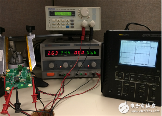
Figure 1: A 100 MHz observer system (measures the LMG5200 switch node, while also converting 24V to 12V at a frequency of 1MHz with a rise time equal to 3ns)
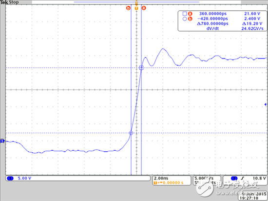
Figure 2: 100 GHz viewing instrument system of the LMG5200 switching node (converts 24V to 12V at a frequency of 1MHz with a rise time equal to 780ns)
Using the previously discussed RSS method, it can be calculated that the measured value of 780ps is still 29% slower than the measured value of the system using the higher bandwidth. In order to accurately determine the rise time (within 1% error), 4GHz system measurement bandwidth is required! If this kind of equipment is available, then the author measured the rise time of 780ps originally could be 600ps - that is the slew rate of 40V/ns! In the next article, I will examine the importance of carefully selected components and layouts to minimize the radiation emissions associated with this dv/dt.
15.6 inch i5 5th Budget Gaming Laptop in plastic is more competitive one in device in 2022, only need around 300usd. However, 15.6 inch 500 dollar gaming laptops is one of the most important top 10 budget gaming laptops, like 14 inch i7 budget gaming laptop under 500, 15.6 inch 11th 512gb laptop, etc.
However, top budget gaming laptops also have other levels, like 15.6 inch i5 laptop 10th generation, 15.6 inch 11th generation laptop i7 512gb, etc. 2022 top laptops under 500 with 14 inch i3 i5 i7 10th you can see here also.
The custom laptop is also of updated, quality hardware, big battery, rich slots, charging by Type C, etc.
Nowadays, the hardware and mature of custom laptop is nearly no difference with brand one, so pls believe you can get a satisfy laptop for your special project, like students project, office project, gaming club etc.
Except laptop, also have custom Android Tablet, Mini PC , All In One PC, 2 In 1 Laptop, also availble.
Any other specail demand, you can contact us and share your requirements details, then matched details sended quickly.
Budget Gaming Laptop,Budget Gaming Laptop Under 500,Top Budget Gaming Laptops,Top Laptops Under 500,Top 10 Budget Gaming Laptops
Henan Shuyi Electronics Co., Ltd. , https://www.shuyicustomtablet.com