As the broadcasting industry continues to accelerate the trend from analog to digital modulation, the degree of system integration continues to increase. Factors such as geographical terrain, antenna gain, directionality, and transmitter power predict coverage and reliability of co-channel interference. The impact is increasing.
The transformation of the launch system for digital modulation formats makes it necessary to rethink the applicability of traditional methods. Our limitations on conventional analog signal research and the current technology of digital modulation and emission system measurements have greatly affected the accuracy and reliability of the test methods. Transmission and other related organizations need to use a monitoring system dedicated to digital modulation to maintain daily transmission stability.
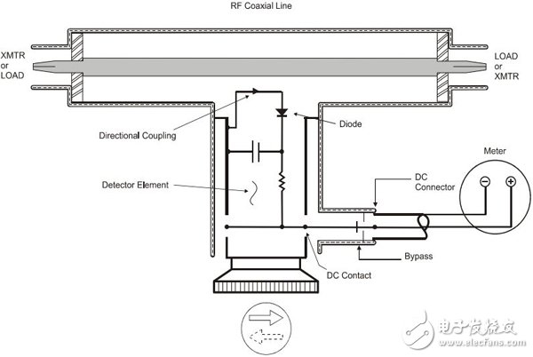
THRULINE® Pass Through RF Power Measurement TechnologyTHRULINE® technology can be translated as "online" or "through", invented in 1952 by Bird's J. Raymond Bird (founder of Bird Electronic CorporaTIon), and its first generation of Model-43 power meters is still in use today.
Pass-through power measurement features:
☆ High-power precision measurement: By means of precise adjustment of the coupler coupling degree and the diode detector integrated calibration method, the overall system meets the working conditions of the detection diode with a true value. The error within the guaranteed calibration range can be controlled under high power measurement conditions.
☆ On-line power measurement: The through-type power meter can be regarded as a section of precision coaxial cable with extremely low VSWR insertion characteristics. After accessing the RF transmission system, it can accurately reflect the RF power measurement status of the current access location.
☆ Integral calibration: Through the patented technology of coupler, detector and display unit, the pass-type power meter is shipped from the factory to ensure that the error level in the calibration range is controllable, which is better than the traditional split-type connection of the terminal power sensor.
The Bird BPME (Broadcast Power Monitor) series of high power sensors offers the possibility of continuous measurement of RF power and VSWR of digitally modulated transmission systems, and provide alarm schemes for important RF power and VSWR thresholds. BPME is the best choice for the measurement of a wide power range and wide frequency range RF communication system.
· Continuous measurement of radio frequency communication systems
· Measuring power reading accuracy of ± 5%
· Support hard contact alarm
Support remote network monitoring, measure digital, simulate multiple modulation types
· Support high frequency band (45-230MHz), multiple power models within 200kW are optional
Support ultra-high frequency band (470~890MHz), multiple power models within 75kW are optional
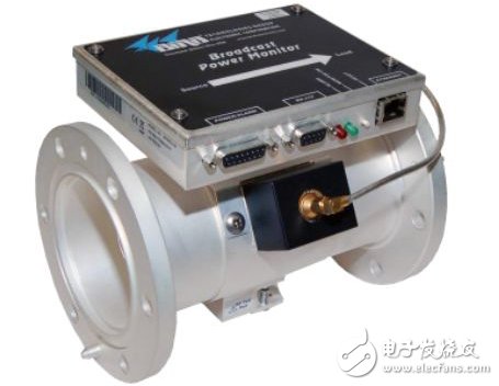
BPME Power Monitor
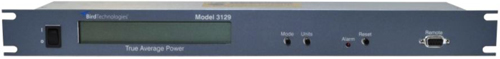
3129 Display
application solution
An advanced mixing system:In advanced combo systems, HD digital broadcasts need to be mixed with analog signals into the end antennas. Therefore, the value of the analog signal power that is coupled into the digital signal generator must be taken into account. BPME's 20dB large dynamic range can easily test the installation and commissioning process of advanced hybrid systems. In advanced combo systems, HD digital broadcasts need to be mixed with analog signals into the end antennas. Therefore, the value of the analog signal power that is coupled into the digital signal generator must be taken into account. BPME's 20dB large dynamic range can easily test the installation and commissioning process of advanced hybrid systems.
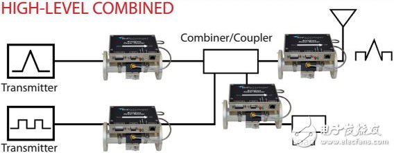
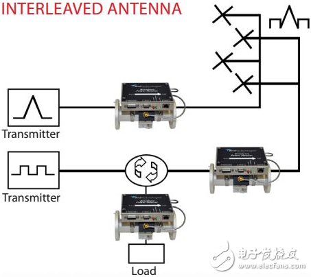
HD digital broadcasting and a set of analog signals can be transmitted simultaneously and separately in a cross-antenna system. Although the isolation from each other is very high, the analog signals that are coupled into the digital signal generator need to be taken into consideration. BPME's unique 20dB dynamic range makes it easy to solve such test problems.
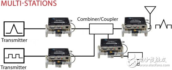
In multi-station transmission, the phenomenon that the end antenna receives signals from several signal generators generally causes a very high average-to-peak ratio. In this kind of system, the ordinary pass type power meter cannot measure the peak value and mean value accurately at the same time, the error is about 20%. BPME can easily measure signal power with a peak-to-peak ratio of 10dB to accurately complete monitoring and deployment tasks.
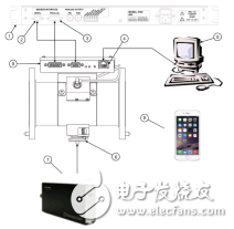
BPME and signal analysis hardware equipment together form the analysis solution for key parts of the system. The 3129 rack-mounted display unit provided by BPME itself facilitates intuitive and intuitive monitoring of parameters. It supports Ethernet protocol to remotely connect servers, stores and analyzes monitoring data, and facilitates remote monitoring and parameter recording in remote locations such as mountains and deserts. The device can easily receive test data at any time; the coupled interface supports access to the signal analysis module for in-depth monitoring and analysis of the transmitter spectrum specifications.
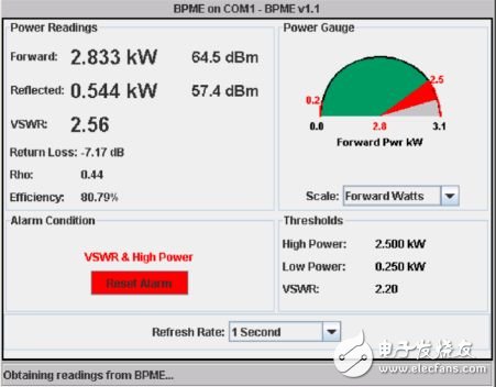
The threshold monitoring interface can reflect the system's reflected power level and standing wave ratio in real time, and can set limit value alarms. Once an abnormal situation occurs, it immediately informs the management staff to handle it, which is convenient for timely warning and avoiding accidents.
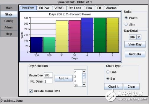
The historical monitoring data comparison and analysis interface can compare the stored parameters in the past with the screen to better feedback the historical wear and tear of the transmission system, and prevent accidents from occurring.
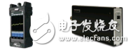
The supporting signal analysis hardware is divided into modular products and handheld products. Supports multiple signal analysis and test functions:
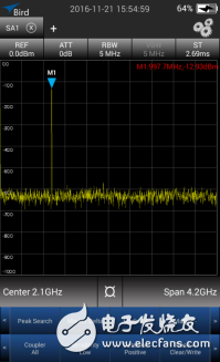
☆ Universal Spectrum TestFundamental analysis of the spectrum can reveal the amplitude information of the signal in different bandwidth frequencies on the screen. Provides broadband testing, including basic spectrum analysis functions such as frequency test, power test, and spurious test.
Occupied bandwidth measures the specific proportion of signal energy in a given frequency bandwidth. The occupied bandwidth allows the best measurement of single-peak signals.
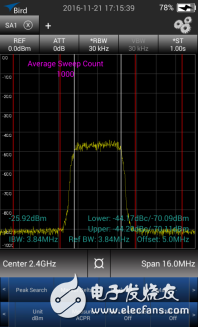
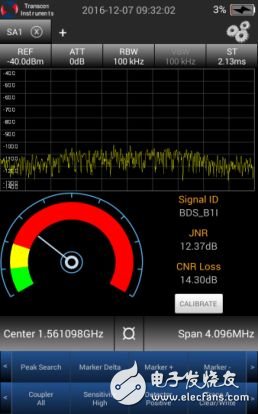
The signal quality of each transmit channel can be separately analyzed, and the signal is characterized by CNR Loss and JNR. At the same time, there is a frequency spectrum display, and the interference signal can be observed visually.
we are the best supplier in China to offer the networking tools including sort of insertion tools, impact and punch down tool (Ericsson punch down tool, Siemens punch down tool, Corning punch down tool and so on), crimping tool(RJ45 crimping tools, coaxial cable crimping tool, picabond ratchet crimper), cable stripper and cutter, Cable Tester and connector removal tool, and so on.
In short, we offer the networking tools for cutting and stripping coaxial cable, twist cable, and optical fiber. And professional compression crimping tool for different connectors, insertion tools for different modules .To save cost for customers, we have desired some tools with multi-function. So you can keep one tool instead of several different types. Meanwhile, for some coaxial cable crimping tool you can change the head to fit the cable specification yourself. It will make you lose weight on tool set but to finish your work perfectly.

Insertion Tool, Punch Tool, Cat 5 Cable Tester, Crimping Pliers, Cable Crimping Tool
NINGBO YULIANG TELECOM MUNICATIONS EQUIPMENT CO.,LTD. , https://www.yltelecom.com