Aiming at the problem of traffic accident caused by information collection, information feedback and information processing mistakes in the corner of the road due to blind traffic, a new and practical emergency warning system for sharp turn vehicles was designed. The CC430F5137 chip with TIMSP430MCU and CC1101 low-power multi-channel wireless RF core is used as the control core. The geomagnetic sensor detects and collects vehicle information. Two large-area electronic display screens in the system give information to inform the warning, and the front car condition feedbacks in time. Going to the driver. Road field simulation tests show that the system compensates for the lack of traditional warning signs for the good detection rate of vehicles in corners. Road safety solutions for sharp turn blind areas have broad application prospects in intelligent transportation.
As society pays more and more attention to civilized driving and traffic safety, people continue to improve the safety of vehicle driving and the construction of intelligent transportation facilities. Among them, the mountainous roads in China have complex terrain, narrow roads, many curved roads and steep slopes. When the vehicle encounters a corner, the driver lacks sufficient understanding of the traffic situation ahead. The short time of the strain will cause the driver to misjudge the traffic and cause a traffic accident. The problem of accidents caused by sharp turn terrain needs to be resolved.
Experts and scholars in the field of transportation mainly research two methods for this problem. The first is to use the curved terrain as a separate research unit. The linear design and optimization design of the curved road, and the analysis of the highway curve and traffic characteristics are obviously the way to cure the symptoms. The second is to scientifically improve road speed limit and traffic safety facilities, enhance the driver's safe driving awareness and standardize the vehicle's qualified inspection management. Although in recent years, China's traffic management departments and road administrations have pre-established a variety of warning slogans and warning signs in the curved terrain, the effect of avoiding traffic accidents is still not ideal.
For traffic safety problems such as sharp turns and steep slopes, it is urgent to use the advanced technologies such as intelligent transportation systems to detect, warn, guide and control road traffic in real time, to achieve safe and orderly road traffic and to ensure driving. The goal of human life and property security. To this end, this paper designs an intelligent warning early warning system for vehicles in sharp turns. It is intended to solve the problem of road vehicles in the cornering area of ​​sharp turns, enhance the reliability of vehicles with sharp turn terrain safety, and reduce the possibility of accidents.
1The design scheme of the early warning system for the sharp turn1.1 The main components of the system design
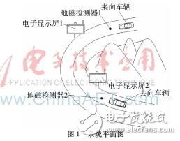
There are two main parts in the sharp turn car reminder warning system. Two geomagnetic sensors are respectively arranged at the front and rear positions of a sharp turn and a certain distance. The electronic display screen is set at the entrance and exit of the curve. The overall system plan is shown in Figure 1, including a pair of inner magnetic field sensors, an oncoming vehicle, a detour vehicle, and a pair of electronic displays. The vehicle geomagnetic detector 2 is mounted on the inner lane, the geomagnetic detector 2 is located in front of the detour vehicle, and the other side of the geomagnetic detector 2 is the electronic display screen 2. In the other direction of the sharp turn road, the vehicle is coming in the outer lane, and the vehicle is now in a blind spot to the vehicle. The sharp turn car reminder warning system gives a safe car solution: a geomagnetic detector 1 is arranged on the road ahead of the vehicle, and the other side of the geomagnetic detector 1 is an electronic display 1, which is displayed on the electronic display 1 To the vehicle information, the electronic display 2 displays the incoming vehicle information. The electronic display informs the driver in advance of the vehicle condition, reminding the driver to turn the vehicle information behind the curve, so that the driver can decelerate in advance and ensure the safety of driving in the corner.
1.2 Comparative analysis of the feasibility of system design
Compared with the widely used wide-angle lens, the warning system of the cornering car is not limited by the viewing angle, and can adapt to various complicated road conditions. For night driving, the foggy and rainy weather has obvious advantages, and can be adapted according to road conditions. Reasonable configuration of the sensor and the orientation of the display module enables the driver to receive the front vehicle condition information early. If there is a vehicle with overspeed or low speed turning, the driver can also know the incoming condition of the blind spot in advance, so as to timely make measures such as deceleration or avoidance.
The geomagnetic sensor detects the distance range covering the entire road width. The sensor detects the vehicle in advance and can preview it on the system display in time, so that the driver can correctly get the information of the incoming vehicle before entering the corner. At the entrance of the curve, the two geomagnetic sensors disturb the signal change due to the two geomagnetic sensors passing through the curve and the exiting curve, so that the single-chip CC430F5137 (CC430) can recognize the vehicle entering and leaving the curve. The speed of time. The time taken by the vehicle to detect the disturbance is detected by a timer inside the single-chip microcomputer, thereby calculating the vehicle speed. The display module releases the vehicle arrival direction and the vehicle speed in real time, so that the driver can decelerate or stop the vehicle in time according to the feedback information of the electronic screen, thereby avoiding an accident in which the vehicle is out of control.
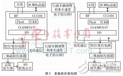
2 system hardware modules and software program designThe hardware design of the system mainly uses TI's CC430F5137 chip. The chip internally uses the MSP430MCU as the control core, and sets the ADC to collect the geomagnetic sensor detection module data. Based on the CC1101 low-power multi-channel wireless RF core, wireless communication is performed through the peripheral antenna and the corresponding electronic liquid crystal display, wherein the point-to-point communication is dialed by the peripheral. The switch sets the address pairing to establish the connection. The overall architecture of the system is shown in Figure 2.
2.1CC430MCU main control module and RF wireless communication module
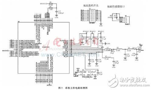
The CC430MCU main control module is the hardware foundation for real-time acquisition of vehicle information. The schematic diagram of the system main control circuit is shown in Figure 3. The MCU has ultra-low power consumption with peak performance up to 25MHz, active mode power consumption is only 160μA/MHz, standby mode (LPM3RTC mode): 2μA, off mode
(LPM4RAM reserved): 1μA, processor 8MHz only 1.3mA. The ultra-low power operation mode increases the service life of the geomagnetic detector. The underground magnetic detector can be used as a power supply for the acquisition system in a separate package.
The external oscillating circuit of the CC430 chip uses a 26MHz crystal oscillator. The program design is controlled by a timer external interrupt by reading the module value of AD. The download port for program debugging uses the most commonly used standard debug interface JTAG interface. The RF transceiver CC1101 uses a carrier frequency based on 433MHz with a suitable impedance circuit.
2.2 Geomagnetic sensor based vehicle detector module
The earth's magnetic field in the vicinity of the geomagnetic detector can be regarded as a uniform magnetic field space. Vehicles generally have ferromagnetic metal materials, and the uniform magnetic field will be disturbed. The geomagnetic detector will collect and analyze the disturbance generated by the magnetic field. A large number of scientific experiments have shown that this disturbance is very sensitive to the magnetoresistive sensor monitoring, so that the presence of the vehicle can be judged, and more accurate magnetic field detection can even detect the time of the vehicle causing the disturbance. The experiment tests the disturbance of the magnetic field by the sports car. It is found that the magnetic field is disturbed when the car passes over the geomagnetic sensor. The specific expression is that the intensity of the earth magnetic field changes significantly in the Z-axis direction. When the vehicle leaves the area near the geomagnetic detector, the earth's magnetic field will return to its previous state. By the disturbance of the magnetic field strength, it is possible to determine whether the parking space is parked or not. A single geomagnetic test will have certain errors and omissions. The system can increase the accuracy of the vehicle speed detection by adding other auxiliary detection means such as photosensitive sensor and image recognition. This article will not go into details.
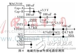
The vehicle ground warning system geomagnetic detector is mainly composed of Freescale's three-axis magnetoresistive signal sensor MAG3110. Built-in high-performance lithium thionyl chloride battery power supply, the main control chip uses a low-power operation mode, and the battery provides a working life of 3 to 5 years for the entire geomagnetic acquisition function circuit board. The geomagnetic vehicle detector is fixed in the middle of the intersection and is injection molded with high-strength ABS and PC materials. It has waterproof, acid and alkali corrosion resistance and anti-collision function. The chip CC430 is mainly placed horizontally at a distance of 0.15m from the side of the geomagnetic detection function printed circuit board to prevent interference of nearby circuit boards on geomagnetic measurement. The schematic diagram of the peripheral circuit of the geomagnetic sensor is shown in Figure 4.
2.3 system software program design and optimization
The hardware design of the system's low-power devices maximizes the efficiency of the battery and extends the life of the geomagnetic detector and master development board. At the same time, flexible power management software programs control CC430 microcontrollers and efficient error correction capabilities are very important.
The data acquisition of the geomagnetic sensor is realized by the MCU port control, and the idle period is in the high impedance state, and the data acquisition is the input or output state. The MCU status of the central receiving node can be scientifically saved by programming. Intermittently receiving data from the probe node, the CPU can also be in low power mode. The LPM3 voltage is 3V and the frequency is 32768Hz. The operating current in this mode is less than 2μA.
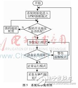
For the first time, the maintenance personnel configure the parameters of the geomagnetic detector (including the serial number of the product, the frequency band of the radio frequency, the transmission power, etc.) by the CC430 MCU through the software. By manually setting the address of the eight-way dial switch for the first time, triggering the configuration mode of entering the fixed frequency band, realizing the parameter configuration and wireless data link of the geomagnetic detector 2 and the electronic display screen 1 (the geomagnetic detector 1 and the electronic display screen 2), completing the vehicle monitoring , wireless inter-transmission, the basic functions of electronic screen display. The software design wireless communication part adopts the SimpliciTI protocol stack design, and the system program flow chart is shown in Figure 5. The system encounters peripheral damage, especially when the geomagnetic sensor detection function is abnormal (or the microcontroller port is abnormally collected), the CC430 MCU will enter the warning reminder mode, and feedback the fault to the electronic display in time to facilitate the equipment maintenance personnel to timely repair.
As we all know that the parents all over the world pay more attention on children education, so more and more businessman do education laptop deals, therefore education laptop is becoming one of the most important fields no matter on customizing laptop or brand one. There are different series according to students ages, 14 inch celeron windows 10 education laptop for elementary students, 15.6 inch j4125 intel education laptop for middle or high school students or normal business jobs, 15.6inch 10th or 11th windows laptops for students in college or professional business or online teaching, etc. Besides, 15.6 inch 10th with 2gb graphics Programming Laptop or 16.1 inch i5 i7 i9 9th HQ GTX 1650 windows laptop for programming also available.
So you just need to share the education laptop price and parameters matched prefer, then right valuable information provide directly for you.
You are always welcome whatever only consult or have purchase plan recently.
Education Laptop,Education Laptop Deals,Windows 10 Education Laptop,Education Laptop Price,Intel Education Laptop
Henan Shuyi Electronics Co., Ltd. , https://www.sycustomelectronics.com