I use the universal experiment board. A circuit demonstrating the function of the CD4067 is produced. This circuit also demonstrates the counter counting process and the generation of the counting pulse. The effect in the classroom teaching is remarkable, which greatly increases the interest of students. The circuit is now recommended to the peers, hoping to have the effect of throwing bricks.
The CD4067 is a CMOS 16-select 1 bidirectional analog switch. It can be used in digital transmission, signal time-sharing processing, multi-channel patrol monitoring and other circuits. It can be easily connected to the I/O port to realize production measurement and control. It can also be connected to other CMOS circuits to form a numerical control network, a multi-channel distributor, etc., and design a variety of practical circuits.
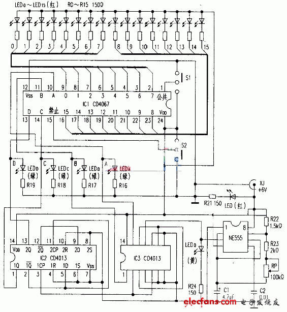
The demonstration circuit consists of a low frequency pulse circuit, a counter and a CD4067 conduction status display circuit. See the attached drawings.
The low-frequency pulse circuit is composed of NE555, R22, R23, RP, C1 and other components to form an oscillator, which generates a counting pulse. Adjusting the RP can change the pulse period. If the resistance of the RP is adjusted to the maximum, the pulse period can be close to 1 s. The student can clearly see the pulse of the continuous output by flashing. If you want to increase the pulse period, you can increase the value of C1 or R23 as appropriate. For the working principle of the NE555 oscillator circuit. There are many introductions, so I won't go into details.

The counting part consists of two CD4013 dual D flip-flops, which are asynchronous counters using 8421 encoding. Light-emitting diodes 1EDD, 1EDC, 1EDB, and 1EDA show the counter's instant count. 1EDD is the highest bit and 1EDA is the lowest bit. “1†indicates illuminance and “0†indicates extinction. The counter sequentially generates 0000 to 1111 digits. It is delivered to the CNC end of the CD4067. Since the counting process is 16 pulses for one cycle. The count shows that the LED flashing rhythm is slower than the pulse output indicator tube 1EDQ, and the student can understand the counter counting process while looking at the number.
The working circuit of CD4067 is very simple, and the 8421 code output by the counter is connected with the CD4067 CNC terminal.
The input (output) terminals of the 0 to 15 channels of the CD4067 are connected to the branches of the LEDs 1ED0 to 1ED15, and the ON state of the CD4067 can be displayed. This circuit only designs a display circuit under transmission conditions, and can only display the current flow when the selection switch S1 is grounded. S2 is a disable switch, dials high, and each channel does not conduct.
When demonstrating the working principle of the whole circuit, the S1 and S2 are all connected to the ground, the external 6V power supply is inserted from the XJ, the power indicating light tube 1ED is on, the oscillation circuit starts to work, and the counting pulse is output. Adjust the RP to make the oscillation frequency the lowest. At this time, 1ED0 flashes once every second, the counter starts counting, and the LEDs 1EDD, 1EDC, 1EDB, and 1EDA follow the principle of 8421 code, and the counter transmits the code to the CD4067 CNC, and then according to the code. In sequence, the 0 to 15 channels of the CD4067 are sequentially turned on, so that 16 LEDs of 1ED0 to 1ED15 are sequentially illuminated, and the illumination time of each of the LEDs is controlled by the counting pulse. Since the counting is continuous, the 16 channels of the CD4067 are turned on in turn, and the operation and functions of the whole circuit can be seen at a glance.
Turn S2 to the high potential end so that the 10 pin of CD4067 is at a high potential. At this point, you can see that the count shows continuous operation.
However, 1ED0~1ED15 are all off, and CD4067 is off.
Then turn S2 back to low, and set S1 to high, so that the current through CD4067 changes direction.
1ED0~1ED15 is off. At this time, the voltage of the output pulse of each channel from 0 to 15 can be measured with a multimeter to verify that the CD4067 has a dual-conducting function.
By adjusting the RP, the oscillation period is accelerated, the luminous tube is quickly flashed, and a feeling of rapid lighting from the beginning to the end occurs. This forms a lantern control circuit. If you change the connection of 0 to 15 channels, you can connect to various forms of lantern control circuits such as cycle, chase, and radiation. You can also use the 16 outputs of the CD4067 to achieve volume control, speed control, dimming, and more.
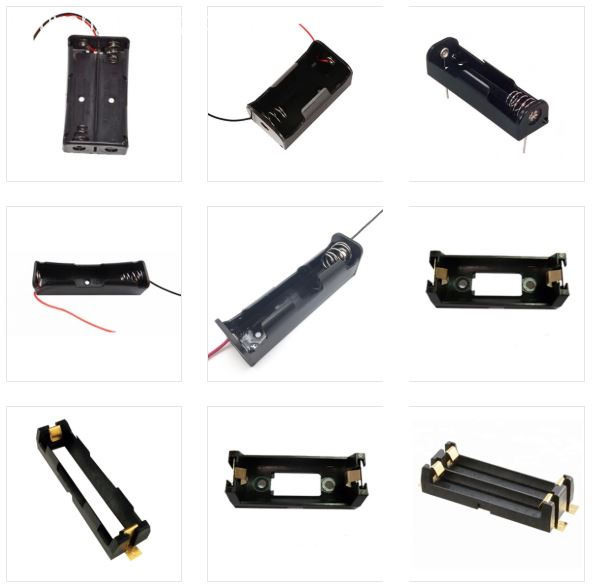
Antenk battery holders for Cylindrical Cells
Thru Hole and Surface Mount or with Wire Leads
For A, AA, AAA, 1/2AA, CR2, CR123A, 1/3N,C, D, N, 12 Volt, 18350, 18650, 26650 Batteries
Antenk Battery Holders for Cylindrical Cells Type
Plastic Cost Effective Holders, Polyproplene base, coil spring contacts
PC Mountable and wire lead for on or off board applications
PC Connetcor for quick connection to automated board assemblies
Snap On Connector for off board connection using 9V connection
High Performance Leaf Spring Holders, High Temp. Nylon Base
SMT Holders, Gold plated contacts
THM Holders, Tin-Nickel Plated Contacts
Solder Lug Holders, for remote wiring applications
High Performance Coil Spring Holders, High Temp. Nylon Base
SMT Holders, Gold plated contacts
THM Holders, Tin-Nickel Plated Contacts

Battery Holder,Cylindrical Cell Holders,Cylindrical Battery Bracket,Custom Cylindrical Cell Holders,Battery Holders Cylindrical,18650 Battery Holders,alkaline batteries Holders
ShenZhen Antenk Electronics Co,Ltd , https://www.pcbsocket.com