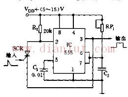
As shown in the figure, 555 and R1, RP1, C2, etc. constitute a trigger delay circuit. Normally, since R1 is connected to VDD, 555 is in the reset state, that is, the 3 pin is at a low level; when the trigger signal arrives, the SCR is turned on, and the 2 pin has a low level signal, so that the 555 is inverted and the output is high. The temporary stability width is Ï„=1.1RP1C2. After triggering, the SCR is turned off. This circuit reduces the need for trigger pulses. If the CMOS type 555 (or 556) is used, the trigger current can also be reduced.
The sensor includes linear encoder and rotary encoder, which is used for the position measurement of speed, displacement and angle. Yuheng optics can provide rotary encoders based on optical, magnetic and gear principles, linear encoders based on optical principles and supporting products.

Custom Sensor,Clintegrity Encoder,Absolute Angle Encoder,Small Rotary Encoders
Yuheng Optics Co., Ltd.(Changchun) , https://www.yhenoptics.com