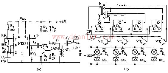
As shown, the circuit consists of a voice-controlled multivibrator, a timing pulse generator, and a thyristor trigger circuit.
555 and R2, RP1, R3, C3, etc. constitute an astable multivibrator. The music signal is passed through the Huhe transformer T1, D1, detection, VT1; amplification, C5 is added to the control terminal 5 of the 555 after DC. The 5 pin is connected to the reference voltage dividing point (VDD) of the internal comparator of the integrated chip, so the upper and lower trigger levels of 555 are respectively
V = 2 / 3 VDD + O. 25 â–³ Vs
V = 1/3VDD + O. 125â–³Vs
The frequency of the output oscillating square wave will vary with the strength of the input music signal. Adjust the RP to change the size of the voice signal. Select a four-D flip-flop with asynchronous set to 0 and set to 1 (such as 74LS74) to form a synchronous counting circuit. Each of the Q terminals of each flip-flop is connected to a driving triode. When Q is high, the triode is turned on, and the thyristor is turned on. , the corresponding lantern will light up. The double-pole switch K connects the counting circuit to a ring shape, and the other knife connects to a four-input NAND gate to avoid the all-zero state. The circuit can produce five different loops, making the flash change with the music accompaniment, suitable for dance and other festive occasions.
Dongguan Tuojun Electronic Technology Co., Ltd , https://www.fibercablessupplier.com