An Kerui Cui Tingyu
Jiangsu Ankerui Electric Appliance Manufacturing Co., Ltd.
Abstract: This article provides an in-depth overview of the fire equipment power supply system, discussing its composition and working principle. It also explores the design standards and relevant regulations for fire equipment power monitoring systems. The case study of the Hangzhou Data Center Building illustrates how the Ankerui fire-fighting equipment power monitoring system is implemented, highlighting its importance in ensuring reliable power supply for critical fire protection devices.
Keywords: Fire equipment power supply; Power monitoring module; Monitoring system; AFPM100
0 Introduction
The AFPM fire-fighting equipment power monitoring system is a standalone computer-based monitoring and control solution developed by Ankerui. It integrates monitoring, alarm, and management functions to ensure the continuous operation of fire protection equipment. This system is widely applicable in various sectors such as intelligent buildings, high-rise residential areas, hotels, commercial complexes, industrial facilities, and key national infrastructure like petrochemical plants, educational institutions, healthcare centers, financial institutions, and telecommunications networks.
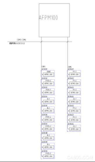
The AFPM100 is the core component of the AFPM monitoring system. It connects multiple sensors via an RS485 bus to create a distributed monitoring network that tracks the real-time status of main and backup power supplies. With a centralized and modular design, it supports voltage, current, and switch status monitoring, along with data storage, analysis, and reporting. The user interface allows for comprehensive monitoring, alarm management, and report generation.
In the Hangzhou Data Center Project, 17 AFPM3-2AV modules were installed across different floors in electrical rooms. These modules are connected to the AFPM100 wall-mounted system using a bus configuration. The system is known for its stable structure, high reliability, ease of maintenance, and cost-effectiveness. Its intuitive interface makes it easy to operate and manage.
1 User Requirements
The project requires the fire equipment power monitoring system to detect faults and abnormal conditions in the power supply of fire protection equipment. It must promptly alert personnel to resolve potential issues, ensuring that fire equipment remains operational during emergencies.
The central host should have the following key features:
1.1 Monitor each circuit’s fire protection equipment based on the power distribution plan, tracking the power supply status.
1.2 Provide a unified monitoring platform that collects real-time data from all system components. It should identify power-related issues such as open circuits, short circuits, over-voltage, under-voltage, and phase loss.
1.3 Enable real-time printing of event details, including location, type, time, and alarm parameters. All alarm records must be stored securely and remain unalterable for fault analysis.
1.4 Comply with GB 28184-2011 and GB 25506-2010 standards for fire equipment power monitoring and control room requirements.
2 Reference Standards
2.1 GB 25506-2010: Fire control room technical requirements. Section 5.7 specifies that the fire power monitor must display power and backup power status and transmit undervoltage alarms to the fire control room.
2.2 GB 28184-2011: Fire equipment power monitoring system standard.
2.3 GB 50116-2013: Design specification for automatic fire alarm systems.
3 System Components
The system includes a fire equipment power monitoring host and detectors. Communication buses connect field devices to the central host. The AFPM100 system uses a two-tier architecture—power status monitor + voltage/current sensor. It ensures accurate detection, safety, and high performance. Internal communication uses RS485, while external communication follows Modbus-RTU. The system is divided into three layers: station control, network communication, and field devices.
3.1 Station Control Management
The station control layer includes the monitoring host, touch screen, and UPS power. It handles data acquisition, processing, and visualization through graphical interfaces. The host manages data transmission and system operations.
3.2 Network Communication Layer
Communication is via shielded twisted pair cables using RS485 and Modbus-RTU protocols for real-time data exchange between field devices and the host.
3.3 Field Device Layer
The field layer consists of AFPM100 series power monitoring detectors that collect and transmit data to the central system.
4 Fire Equipment Power Components
4.1 AFPM100 Fire Protection Power Host
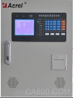
Technical specifications include AC220V 50Hz main power, DC24V for sensors, 24-hour operation, and Modbus-RTU communication. It supports remote reset, parameter adjustment, and user management. Environmental conditions range from -10°C to 55°C, with humidity up to 95%.
4.2 AFPM100 Series Instruments
Features include real-time voltage monitoring, over/under voltage and phase error alarms, switch input monitoring, relay output, event logging, and compatibility with Modbus-RTU. It offers high integration, networking, and intelligence.
5 System Functions
5.1 Monitoring and Alarm Function
Monitors switch status, voltage, current, and alarm information. Alarm response time is ≤100s. Sound and light signals can be manually silenced.
5.2 Control Output Function
Supports remote control of relays for individual or all devices. Output contacts are normally open with AC250V 3A or DC30V 3A capacity.
5.3 Fault Alarm Function
Detects disconnections, short circuits, undervoltage, overvoltage, and other faults. Fault signals are distinct from regular alarms. Response time is ≤100s.
5.4 Self-Test Function
Includes connection checks and equipment self-tests. Self-test duration is ≤60s.
5.5 Alarm Recording Function
Stores up to 10,000 alarm events with details like type, time, and description. Allows querying and printing of records.
5.6 Print Function
Supports Chinese character printing for alarm and fault events.
5.7 Silence Function
Mutes sound alarms upon pressing the "silence" button. If new faults occur, the alarm reactivates.
6 Conclusion
The fire equipment power monitoring system in the Hangzhou Data Center Project includes the AFPM100 monitoring device and power detectors. It ensures real-time power monitoring, fault detection, and alarm alerts. The system is reliable, user-friendly, and adaptable for various applications.
References
[1] General Technical Requirements for Fire Control Room. Beijing: China Standard Press, 2011.
[2] "Fire Equipment Power Monitoring System". Beijing: China Standard Press, 2011.
About the Author: Cui Tingyu, male, bachelor's degree, works at Jiangsu Ankerui Electric Appliance Manufacturing Co., Ltd. His research focuses on intelligent building power supply and distribution monitoring systems. Email: el.cn | Mobile: [phone number] | Website: http://[website].
3.7V Lithium Battery,Rechargeable Battery Pack,consumer rechargeable battery
Shenzhen Jentc Technology Co., LTD , https://www.phenyee.com