Abstract: This paper proposes a design scheme of capacitor buck low-power LED driving circuit based on constant current diode. It is powered by AC mains and outputs low-voltage constant current. It only needs to adjust some component parameters in the circuit to drive different power LED lights with constant current. group. This design introduces a constant current diode based on the traditional capacitor step-down drive circuit to ensure the low-voltage constant current output of the drive source. Loaded low-power LEDs are connected in a cross-array manner, reducing the light-off rate.
Keywords: circuit and system; white LED; drive circuit; constant current diode; capacitor step-down; LED array
0 Preface
In recent years, the luminous efficiency of LEDs has increased by 100 times and the cost has been reduced by 10 times. It is widely used in backlight, signal display, lighting and other fields. In the LED light source and market development, the development and application prospects are white LEDs, which are economical for solid lighting devices and are environmentally friendly, and are gradually replacing traditional incandescent lamps.
Due to the low price, low heat generation and high luminous efficiency of low-power white LEDs, they have been widely applied to general lighting and landscape lighting. Therefore, there is an urgent need for the design and performance improvement of low-power LED driving power supplies. LED illuminators are usually powered by mains. Due to the low operating voltage of LEDs and low current, driving LEDs with mains to solve the buck and rectification problems requires higher efficiency, smaller size and lower cost. LED is a current-driven device whose brightness is proportional to the forward current. In order to ensure efficient and uniform LED illumination, the LED driver should be a constant current output. Therefore, designing an efficient, simple, and inexpensive LED driver has become a research hotspot. In this paper, a low-power LED driving circuit based on constant current diode is designed. The power frequency is supplied by the mains and the output current is constant.
1 LED connection method
When designing an LED lighting system, it is necessary to consider what kind of LED driver to use, and how to connect the LEDs. Only a reasonable matching design can ensure the normal operation of the LED. The low-power white LEDs typically have a forward voltage range of 2.8 to 4 V and an operating current of 15 to 20 mA. LED lamps for illumination are typically a plurality of such low power LEDs that are combined in series and parallel fashion, and these LEDs typically need to be matched to produce uniform brightness. It is also necessary to connect these LEDs together in a reasonable manner. The entire LED lamp group cannot be operated because one of the LED lamp beads is damaged.
A plurality of LEDs of the same type are connected in series, and the current flowing through each LED is equal. When the LEDs are in poor agreement, although the forward voltages of different LED beads are different, the current flowing through each LED is equal, and the brightness of each LED bead will be the same. LED series connection drive source output voltage requirements are large, the current must be constant below 20 mA. When one of the LEDs is disconnected due to poor quality, the entire LED lamp group will not light, which requires high quality and soldering process for the LED lamp bead.
All the LED beads are connected in parallel, and the driver needs to output a large current, and the output voltage is about 3 V. Parallel connection avoids the serious drawback of extinguishing the entire lamp group after one LED burns out. Since the luminous intensity of the LED is proportional to the operating current, there are certain differences between the parameters of the LED lamp bead, and the current flowing through each LED bead is inconsistent, which directly leads to uneven brightness of the LED. When driving parallel LEDs in constant current mode, the LED lamp beads should be connected in parallel as much as possible to prevent the current flowing through other LEDs from burning out due to the burning of several LEDs.
In order to improve reliability and uniformity of illumination, a cross-array connection method is proposed, and FIG. 1 is a diagram of an LED cross-array connection mode.
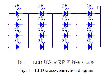
It can be seen from the figure that when the individual LEDs are short-circuited or open, the entire lamp group will not be extinguished. The cross-array connection method has the characteristics of simple circuit, stable brightness, high reliability, and low driving requirements.
2 low power LED drive circuit design
2.1 Capacitor Buck Circuit
When the LED is powered by AC mains, it must be converted to low-voltage DC by AC/DC and DC/DC conversion. Currently, the step-down circuit mainly has a power-frequency transformer linear step-down circuit, a high-frequency switch circuit, and an IC-based Buck circuit, capacitor step-down circuit and so on. Considering the size and cost of the driving power supply, this paper uses a capacitive step-down circuit. Figure 2 shows the capacitor step-down circuit:

In Figure 2, the charge and discharge current of the non-polarity step-down capacitor C1 is IC=2πfCU0 (U0 is the AC voltage, f is the AC frequency), and the current I0 supplied from the step-down capacitor C1 to the load is actually the charge and discharge current IC flowing through C1. . When the load current is less than the charge and discharge current, the excess current will flow through the filter capacitor C2. If U0=220 V, f=50 Hz, IC=69C (IC is mA, C is μF). In order to ensure safe and reliable operation of the step-down capacitor, the withstand voltage should be greater than 2 times the mains voltage, so the step-down capacitor should use a monolithic capacitor with a withstand voltage of 630 V. R1 is a 1 MΩ discharge resistor. When the circuit is powered off, C1 is quickly discharged through R1, and D1—D4 is a full-wave rectifier bridge consisting of IN4007. In order to obtain better filtering effect, the capacity of the selected filter capacitor should satisfy RLC=(3~5)T/2 (RL is the load resistance, T is 0.02 s), and the withstand voltage should be greater than 1.1 2 U0 (U0 is the capacitor) Buck circuit output voltage). In principle, the larger the capacitance value is, the smoother the output voltage is, the smaller the ripple value is. However, as the capacitance increases, the volume generally increases. When considering the board area, a large-capacity filter capacitor should be selected.
2.2 Mains-powered low-power LED drive circuit
The mains power supply low power LED drive circuit based on constant current diode is shown in Figure 3:
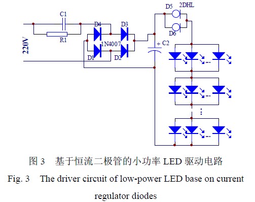
In the figure, D5 and D6 are constant current diodes. The constant current diode used in this design is the 2DHL series of Guizhou Bo Yue Company. The 2DHL series of constant current diodes is a basic electronic device made of silicon.
The positive constant current is turned on and the reverse is turned off. The output has a large constant current, high precision, and low starting voltage. The device is connected to the circuit loop according to the polarity, and the constant current effect can be achieved. The application is simple, and the two-terminal constant current source in the circuit theory and circuit design is realized. Due to the large output current, the load can be directly driven to achieve a constant current supply. Widely used in LEDs, semiconductor lasers, and where constant power supply is required. It has low starting voltage (3~3.5 V), wide constant current voltage range (25~100 V), fast response time (tr < 50 ns tf <70 ns), and negative temperature coefficient. In order to provide a larger current, a plurality of constant current diodes can be used in parallel, and after parallel connection, the output current is the sum of the nominal currents of the respective constant current diodes. Due to the increased operating voltage range of the constant current diode, even if the load LED is short-circuited, the entire drive circuit will not be burned, and the circuit protection function is strong.
The low power LED has a forward voltage of 2.8~3.2 V and a maximum operating current of 20 mA. The LED brightness L is proportional to the forward current IF:
mL = KI F (K is the proportional factor) [6], the higher the operating current, the greater the brightness, but since the LED also has brightness and saturation characteristics, the LED forward drive current should be less than its standard current. After the low-power LED current reaches 15 mA, the brightness is saturated. If the current continues to increase, it will not increase the brightness, but will also cause the LED's PN temperature to rise rapidly and cause light to decay.
C1 is a step-down capacitor. The output current of the capacitor step-down circuit is mainly related to the capacity of the step-down capacitor and the output voltage. The higher the output voltage, the smaller the current. Theoretically, the output voltage of the driver circuit can reach more than 100 V. However, considering the large size of the filter capacitor C2 at high voltage, it is not easy to install the circuit. The drive circuit designed in this paper mainly uses 50 V and 100 V filter capacitors. Although the larger the capacitance value, the larger the output current of the driver circuit, the larger the value of the step-down capacitor will reduce the safety characteristics and stability of the entire driver circuit. Therefore, it is recommended that the capacitance of the step-down capacitor should not exceed 3.3 μF. Table 1 below shows the currents supplied by the drive circuit at different voltages and the maximum number of LEDs that can be driven using 0.68~3.3 μF different size step-down capacitors. (The data in this table is obtained from multiple experiments and simulations).

The LEDs are connected in a cross-array manner. The same number of LEDs are connected in parallel, and the groups are connected in series. With the cross-array method, the LED lamp bead consistency is not high, and the entire LED lamp is not extinguished because one of the lamp beads is damaged. Due to the fact that the white LED spectrum component is single and the softness is poor, in order to improve the overall lightness and softness of the LED lamp, several yellow LED lamp beads should be appropriately added in the white LED lamp.
3 Simulation and experimental analysis
3.1 Pspice simulation of the drive circuit
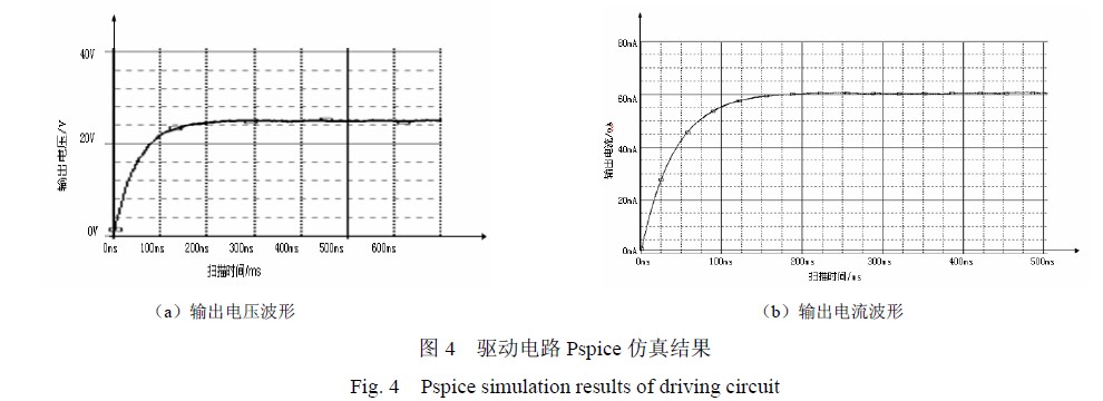
In order to verify the feasibility of the driver circuit, the circuit was simulated using the pspice circuit simulation software. Figure 3 shows the output voltage and current waveforms during transient analysis. The buck capacitor C1 in the driver circuit has a capacity of 1 μF, the filter capacitor C2 has a capacity of 1000 μF, a 2DHL060 constant current diode (constant current 60 mA) is connected in series, and the output drives 28 0.06 W white LEDs (using 4*7 cross-connection) ).
It can be seen from the figure that the circuit enters a steady state at 100 ms. After stabilization, its output voltage is 25V and the output current is constant at 60 mA. The feasibility of a low-power LED driver circuit based on a constant current diode is basically verified.
3.2 Experimental analysis
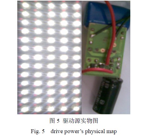
To further verify the feasibility of a low-power LED driver circuit based on a constant current diode. A drive source for driving 65 (5*15 mode) 0.06 W white LEDs was fabricated, in which the step-down capacitor C1 was 1.5 μF, the filter capacitor C2 was 1000 μF, the constant current diode was connected in parallel with two 2DHL040s, and the current was multiplied by a multimeter. The voltage is measured. The actual measured input voltage is constant at 80 mA in the range of 196~248 V, which is equivalent to 16 mA flowing through each LED. At 219 V input voltage, the entire circuit consumes 7.1 W, and the power factor of the drive source is 0.47. Figure 5 is a physical diagram of the fabricated low power drive source.
4 Summary
The low-power LED driver circuit based on constant current diode designed in this paper is simple in structure, low in cost, and meets the requirements of LED constant current driving. After many experiments, the reliability of the driving circuit is very high. It can be used as a power source for a variety of LED luminaires by changing the step-down capacitor.
Although the drive circuit power factor is low, it is particularly suitable for low-end lighting market applications. The LED has higher luminous efficiency than the traditional light source, and the low-power LED lamp can be compared with the high-power fluorescent lamp. Therefore, the LED lamp using the driving source is energy-saving overall.
The main innovation point: the constant current diode is introduced on the basis of the traditional capacitor step-down drive circuit to ensure the low-voltage constant current output of the drive source.
Loaded low-power LEDs are connected in a cross-array manner, reducing the light-off rate.
references:
[1]. C1 datasheet http://+_2455447.html.
Embedded Industrial Touch Pc is a good device for harsh environment such as factory automation, transportation, facility management, networking and public works.
The industrial multi-touch PCs are made of all metal case, with latest Projected capacity touch screen and a 3 mm thickness glass, reliable, durable, and provide industrial OEMs and machinery manufacturers with vast selection of industrial embedded touching and computing solutions that help customers with a variety of applications.
We provide embedded bracket for free.
Interactive Computer,Embedded Computer,Embedded Touch Screen Panel Pc,Embedded Industrial Touch Pc
Guangzhou TouchWo Electronics Co.,Ltd. , https://www.touchaio.com