1, LMK0480X power supply circuit introduction
The LMK0480X series clock products are TI's recent clock jitter filter chips, which use a two-stage phase-locked loop cascade architecture. The first-stage phase-locked loop mainly uses a narrow-band loop filter to filter out the phase noise and spurs of the reference input (CLKin), which acts as a clock debounce, and uses an external VCXO to generate a clean system reference clock. The second-stage phase-locked loop mainly uses the first-stage output as its reference clock to generate various clock frequencies required by the system, while meeting the phase noise, jitter and spur requirements required by the system design. In practical applications, the selection of external VCXO, the design of the loop filter, and the optimization of various loop parameters have a significant impact on the final clock performance. In addition to these factors, the power supply design of the chip is another important part of the application. Improper design will directly lead to the output clock not meeting the system requirements, especially for applications with high jitter and glitch requirements.
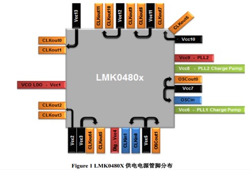
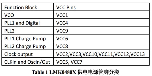
The distribution of the power supply pins of the LMK0480X chip is shown in the above figure and can be roughly divided into the following categories:
In this chapter, the main design of the power supply design of the internal module circuit of the LMK0480X chip is introduced. In the next chapter, the actual experiment will be combined to detail the impact of the power supply noise of the LMK0480X on the actual performance.
2, LMK0480X power supply design and PSRR performance test
2.1 LMK0480X power supply design principle
For different types of power supply pins, the requirements for external power supply circuits are different. The general principles to be followed are as follows:
• LMK048XX has an integrated high frequency decoupling capacitor inside all the power supply pins. Since this capacitor is closer to the chip, it can eliminate the influence of the parasitic inductance of the package bonding line. The decoupling effect is better than the external high frequency decoupling capacitor ( "1nF" is more effective. At the same time, the external decoupling capacitor easily introduces some high-frequency interference from the ground plane into the power supply pin of the chip. Therefore, it is generally not recommended to add 1nF decoupling capacitor to all the power supply pins of the LMK0480X.
• The internal circuits of the chip that VCC1, VCC4, and VCC9 are responsible for do not generate noise, so the three power supply pins can be connected together to share the power supply circuit; there is no need to increase the bead isolation pin and the total power supply circuit because of the magnetic The beads easily affect the power supply of the VCO (VCC1) and form a bulge at the output.
• VCC6 and VCC8 supply power to the charge pump of the two stages of phase-locked loops. This is critical to the final performance of the chip. A separate power supply branch is recommended. For VCC6, since the phase-locked loop is supplied to the first-stage phase-locked loop, the phase-detection frequency of the first-stage phase-locked loop is relatively low, so the magnetic beads of the power supply branch can be omitted, and VCC6 can be directly connected to VCC1 directly. /4/9 circuit. For VCC8, in order to increase the loop bandwidth, the phase-detection frequency of the second-stage phase-locked loop is relatively high ("50MHz"). In order to prevent the phase-detection frequency from leaking to Other power supply pins, VCC8 is required to have independent power supply branches. At the same time, the beads should be added to isolate the interference of VCC8 and the main power supply circuit. When the phase discrimination frequency is low, consider removing this magnetic bead.
• VCC5 and VCC7 primarily supply power to the chip's reference and VCXO's inputs and outputs, as well as to the PLL2's lockout circuitry. For these pins, no external large decoupling capacitors and beads are needed to prevent some ground plane interference from stringing into the power pins, thus affecting the lock indication of PLL2.
• VCC2, VCC3, VCC10, VCC11, VCC12, VCC13 supply power to the chip's 12 outputs (one supply pin is responsible for two outputs). If several of them output the same frequency, these power supplies can be connected together to share the power supply branch and simplify the design. Since the output frequency is relatively high, it is recommended to add magnetic beads to these power supply pins to reduce the influence of chip switching noise on the overall power supply of the chip and improve the isolation between the channels. At the same time, as mentioned earlier, since the high-frequency decoupling capacitor is integrated inside the chip, no external decoupling capacitor is needed.
When the output frequency is low (<10MHz), or when outputting a single-ended LVCMOS or high-swing LVPECL signal, in order to reduce the impedance of the power supply loop, it is recommended to remove the magnetic beads or add a larger decoupling at the pin. Capacitor, providing switching current.
• When the output clock type is LVPECL, the output should be protected from capacitance to ground. Because it is easy to form a short circuit to the ground, not only does the power pin require a large switching current, but also introduces frequency noise to the ground plane, causing interference to the system.
2.2 PSRR (Power Supplier RejecTIon RaTIo) performance analysis
In order to characterize the influence of power supply noise of various power supply pins on the output noise of LMK0480X, the power supply noise rejection ratio PSRR is usually used to characterize the power supply noise immunity of the phase-locked loop chip. This section evaluates the power supply noise suppression of the LMK0480X through actual test examples. performance.
2.2.1 Test setup
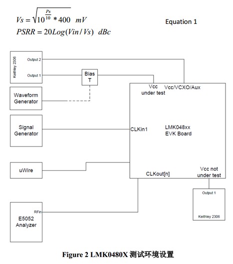
The PSRR test is based on the LMK0480X evaluation board. In these tests, the test block diagram is shown in Figure 2 and is set as follows:
1. The external VCXO is powered by a separate, clean power source, eliminating the effects of VCXO on test results.
2. Remove the decoupling capacitors and beads outside the chip to eliminate the effects of these devices on the PSRR of the chip.
3. The source of the interference is combined by the signal generator to the power pin of the test. The frequency of the interference source is continuously scanned from 50KHz to 2 MHz, and the interference signal is tested inside and outside the loop bandwidth, which has different effects on the performance of the chip PSRR.
4. The amplitude of the interference source input signal is fixed at Vin = 100mV; measure the power Ps dBm of the spurs (offset corresponding to the interference source frequency) caused by the corresponding interference sources on both sides of the output port carrier, and convert Ps into voltage. The amplitude Vs, the conversion formula, and the PSRR calculation formula are as shown in Equation 1.
A Battery Management System (BMS) is any electronic system that manages a rechargeable battery (cell or battery pack), such as by protecting the battery from operating outside its Safe Operating Area, monitoring its state, calculating secondary data, reporting that data, controlling its environment, authenticating it and / or balancing it.
A battery pack built together with a battery management system with an external communication data bus is a smart battery pack. A smart battery pack must be charged by a Smart Battery Charger.
Battery Management System
Battery Management System,Bms Battery Management System,12V Battery Management System,Lipo Battery Management System
Xinxiang Taihang Jiaxin Electric Tech Co., Ltd , https://www.agvchargers.com