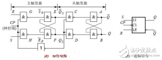
Figure 1: Master-Slave SR Flip-Flop Circuit
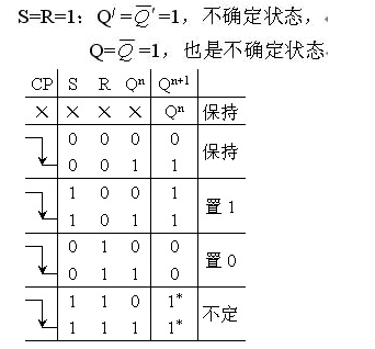
Constraint: SR = 0
In summary, the operation of the master-slave SR flip-flop shown in Figure 1(a) occurs in two steps. First, when CP transitions from 0 to 1, the main trigger receives input signals and changes its state. During this time, the slave trigger is blocked, so its output remains unchanged. This phase is known as the preparation stage. Second, when CP transitions from 1 to 0, the main trigger becomes inactive, while the slave trigger is activated. It captures the current state of the main trigger and updates its output accordingly.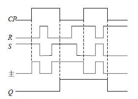
Figure 2: Working Waveform of SR Flip-Flop
During each cycle of the CP signal, the flip-flop only changes its output at the falling edge of the clock. This method of triggering is called pulse-triggering. As a result, the flip-flop avoids unintended state changes. Figure 2 illustrates the operating waveform of the master-slave SR flip-flop. In Figure 1(b), the small circle “〇†at the CP terminal indicates that the flip-flop is triggered by the falling edge of the clock signal.Industrial Main Board Cable:SCSI,D-SUB,DVI,Wire to Wire ,RJ45...
There are five types of main board power line interface, and different external devices correspond to different interfaces. Different interfaces and their connecting pins are also different. For example, the pin of the main power supply is 24 pins, and the hard disk drive is 5 pins.
1. 20pin + 4Pin interface: it is a common interface combination, in which 20pin is the main power interface and 4Pin is the auxiliary power supply interface.
2. 5pinsata interface: special interface for power supply of hard disk and optical drive.
3. 6pin? PCI? Express connector: a special interface for independent graphics power supply.
4. 4Pin connector: it is a kind of floppy disk power connector, which is used to power the floppy drive equipment.
5. 4Pin power interface: optical drive, old IDE hard disk and peripheral hardware power supply interface.
Industrial Main Board Cable
ShenZhen Antenk Electronics Co,Ltd , https://www.antenk.com