Introduction Radio Frequency Identification (RFID) technology is an emerging non-contact automatic identification technology with broad application prospects in many fields such as industrial automation, commercial automation, transportation control management, anti-counterfeiting and military. It uses wireless radio frequency for non-contact two-way data communication to achieve the purpose of identifying and exchanging data. It can be used to track and manage almost all physical objects. RFID electronic tags have become the main direction of the development of global automatic identification technology in the 21st century. At present, RFID has been widely used, and there are several international standards such as ISO10536, ISO14443, ISO15693, ISO18000, EPC Global and so on. Among them, ISO18000-6C belongs to the UHF radio frequency identification technology standard, which incorporates the EPC C1G2 standard. The standard is characterized by high speed, and the number of tags that can be read at the same time. In theory, more than 1,000 tags can be read; the function is strong, and there are multiple write protection modes; the security is strong.
In China, due to the late start of RFID technology, the field of application is not very wide. The main applications are based on medium and low frequency applications, including vehicle management and access control. At present, UHF radio frequency identification technology and its application are in the primary development stage in China, and there is no mature UHF electronic tag chip design technology in China.
Here, first introduce the working principle of the electronic tag and the ISO18000-6C standard, and design the overall circuit to realize the UHF electronic tag verification platform according to the ISO18000-6C standard. Focus on the design and implementation of the digital baseband part based on EP1C6Q240FPGA. Finally, the test results of the platform are given, which verifies the correctness and reliability of the platform design.
This article refers to the address: http://
1 How electronic tags work Radio frequency identification systems usually consist of a reader (Reader) and a radio frequency tag (RFID Tag). The radio frequency tag attached to the object to be identified has electronic data in an agreed format as the identification information of the item to be identified. The reader can read out the electronic data stored in the tag or write the information into the tag without contact, thereby realizing automatic identification and management of various objects. The reader and the radio frequency tag communicate with each other using advanced radio frequency technology according to the agreed communication protocol, and the basic communication process is as follows.
(1) The tag in the range of the reader/writer receives the carrier energy sent by the reader, and is powered on and reset;
(2) The tag receives the command sent by the reader and operates;
(3) The reader issues a selection and an inventory command to identify the tag,
A single tag is selected for communication, and the remaining tags are temporarily in a sleep state;
(4) The identified tag executes the access command sent by the reader, and sends the data information to the reader through the backscatter modulation mode, enters the sleep state, and then no longer responds to the reader;
(5) The reader continues to search for the remaining tags, repeating (3), and (4) waking up individual tags for reading. Until all the tags are identified.
The tag transmits data to the reader through the backscatter modulation technology. For the passive electronic tag, there is not enough transmission energy itself, so the antenna's reflection intensity is controlled by changing the matching impedance of the antenna, and the antenna reflectance is obtained when the impedance is not matched. Very large, the antenna reflectivity is small when impedance matching, in order to indicate the presence or absence of the output signal.
2 ISO18000-6C standard ISO18000-6c standard is:
The operating frequency tag shall be capable of receiving power from the reader in the frequency range of 860 to 960 MHz and capable of communicating with the reader.
The modulation reader should communicate using DSB-ASK, SSB-ASK or PR-ASK modulation. The tag should be able to demodulate the above three types of modulation. Label backscattering should be done with ASK or PSK modulation. The tag merchant chooses the modulation form. The reader can demodulate the above two types of modulation.
The link from the data encoding reader to the tag shall be PIE encoded, and the tag encodes the reflected scattered data into the subcarrier FMO baseband or Miller modulation of the data rate. The reader issues a command to encode the selection.
The data rate reader-to-tag data rate is selected based on the Tari value, which can range from 40 to 640 Kb/s. The reflection rate of the label is determined by the following two formulas:

3 The overall design and implementation of the RFID board-level label verification platform The board-level label is mainly composed of analog RF and digital processing. Figure 1 is a block diagram of the board-level electronic tag verification platform.
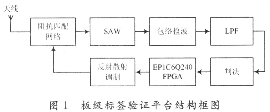
The analog RF part is implemented by discrete components to complete the reception of the RF signal. The signal from the RFID reader passes through the antenna and the impedance matching network, and is filtered by the 915 MHz acoustic surface filter to perform envelope detection and then through an operational amplifier. A first-order active low-pass filter is used to complete the high-low level decision by the voltage comparator. The digital part is realized by EP1C6Q240FPGA, and the ISO18000-6C protocol is processed. The EP1C6Q240FPGA receives the TTL level from the front end and completes functions such as PIE decoding, CRC check, command parsing, state transition, data storage, and FMO encoding. FMO coding is achieved by inverting the scatter modulation output and changing the reflected impedance of the antenna.
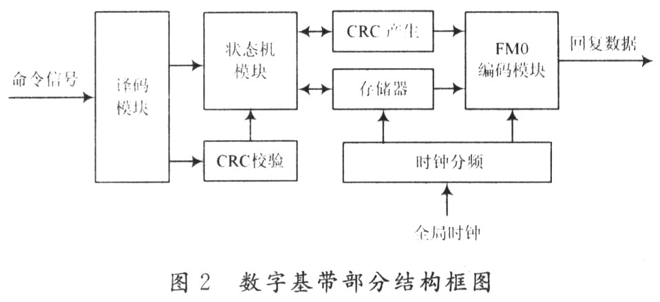
The design of the digital baseband portion is implemented on Altera's EP1C6Q240 FPGA. After in-depth study of the protocol content, the digital part of the tag adopts the Top-down design method. Firstly, the circuit function is described in detail, and the whole system is divided according to the function; then the VExilog hardware description language is used for RTL code design. The digital baseband structure block diagram is shown in FIG. 2, which includes a decoding module, a Cyclic Redundancy Check (CRC) check module, a state machine module, a CRC generation module, a memory, an encoding module, and a clock frequency dividing module. The decoding module receives the command signal demodulated by the analog portion, decodes the signal into binary data identifiable by the digital portion of the tag according to the command format specified in the protocol, and sends the signal to the CRC check module and the state machine module. The CRC check module performs integrity check on the received command. If it is confirmed as a valid command, the state machine module is triggered, and the control tag performs corresponding operations, such as reading and writing memory, anti-collision control, and the like. After the processing is completed, the data to be sent is sent to the CRC: the generating module generates a corresponding CRC check code, and then sends the data to be sent together with the check code to the encoding module, and finally the encoding module sends the simulation to the analog pulse. After some processing, it is sent to the reader by RF technology.
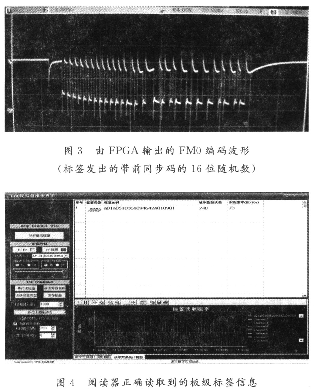
4 Test Results Quartus II 6.0 is a comprehensive integrated design platform for Altera FPGA/CPLD. The platform integrates the tools needed for virtually any design flow, including design input, simulation, logic synthesis, place and route and implementation, timing analysis, chip download and configuration, and power analysis. Verilog HDL program in QuartusII6. Compilation, simulation and download in O environment, board-level label can be combined with ISO18000-6C-compliant reader (Cetc7 Rlid Reader V) after overall design, PCB board design and implementation, code design, simulation and download, and system debugging. 1.O) Communicate, send and receive information quickly and accurately, and implement anti-collision function. Figure 3 shows that the board level tag can decode the command information from the reader and correctly output the FM0 coded signal under the control of the state machine. Figure 4 shows that the board-level tag can correctly read the ISO18000-6C standard reader (the EPC code is consistent with the tag), and the reading effect is good (73 times/10 s), and the reading performance is stable. Tests show that the board-level label can realize the reading and writing function in the ISO18000-6C standard, the label work performance is stable, and the reliability can achieve the expected effect.
5 Conclusion According to the ISO18000-6C standard, using EP1C6Q240FPGA and analog RF discrete components, after the overall design, PCB board design and implementation, code design, simulation and download, and system debugging, complete the FPGA-based board-level label software and hardware Design and implementation. The system has been tested, has been able to work properly, has excellent read and write performance, and has achieved anti-collision capabilities. On this basis, the security and reliability can be further improved. The designed tag digital circuit RTL code can be directly applied to the development of the tag chip, which provides a strong guarantee for the next step to design an electronic tag chip that conforms to the standard.
our main Cooking Tools are Electric Wine Opener /Automatic Wine Opener/Automatic Wine Corkscrew with Foil Cutter .it can make open the wine bottle Every easy.
we make some Rechargeable Wine Opener and some Electric Wine Opener work with Dry Battery (not indclude battery).
This kinds of Multi-Function Electric Wine Opener is very easy to operate and labor-saving.
This Electric Wine Opener as Bar Toos and cooking tools is very nice.
Gift Box package with Foil Cutter ,Pourer ,Vacuum Stopper as a present is very nice.
Gift Sets
Wine Gift Set, Wine Opener Gift Set, Business Gift Set, Champagne Gift Set
Ning Bo LingSheng Electric Appliance co., Ltd , http://www.lsautotools.com