2. Digital control signal It is the use of digitally encoded bit signal control information (including parameters and addresses), including a multi-data control signal, usually used in modern computer lighting and digital control equipment. Its biggest advantage is: using a signal line can quickly and accurately transmit dozens of hundreds of optical information to the corresponding equipment, and the transmission distance is very long, high anti-interference, the same type of digital control signal can also It's easy to combine with each other. Its disadvantages are that the corresponding coding and receiving equipments are more complicated, and under the existing technical conditions (encoding and processing technologies), the information it can hold is still limited. There are two commonly used digital control signals:
1) lRS232 digital signal (aka PMX)
It is a serial digital coded signal, introduced by the British pulsar company. A 3-core or 5-core XLR connector is typically used, where 1 is the shield ground and 2 and 3 are signal paths. This signal is mainly used in pulsar consoles and lamps and silicon boxes that accept this signal.
2) DMX512 digital signal It is also a serial digital coded signal. Due to its wider use, it has gradually become a standard for lighting control signals. With the existing transmission ratios and signal processing capabilities, it can transmit optical output signals to 512 optical paths. When using the DMX512 digital signal, in order to ensure accurate signal transmission, it is necessary to use a termination resistor at the end of the signal line.
3. Address Coding Address Coding is a concept that occurs simultaneously with digital control signals. It refers to the determination of lamps or other lighting-driven equipment in a specific position controlled by a digital signal, that is to say: in the lighting equipment signal control system to give them a number similar to the address.
The address code can express the actual position of the luminaire in the system, that is, the true address code: it can also express the starting position of the channel contained in the luminaire in the system. The exact address should be the limbs of the channel. In general, address encoding is accomplished by means of an address encoder, which generally uses a plurality of two-level DIP switches on the address encoder for address setting.
For the address coding, it is necessary to explicitly point out: 1, 2, 3, 4, ... on the general address encoder. . Waiting for several consecutive numbers refers to the encoder's DIP switch number, not the actual address code. The difference between the address code and the DIP switch value is easier to understand. Because the digital signal adopts the binary code way, the address code also melts this kind of thought, it uses the opening and closing of the corresponding DIP switch to achieve the purpose of digital coding.
in fact. The address code corresponding to the Nth DIP switch is regular, that is, 2n-1, which is an exponential form of 2.
In addition, the address coding is in the form of the sum of the address codes corresponding to the DIP switches. For example, the address code corresponding to the above address encoder should be 1+4+8=13, which means that this address code setting is the thirteenth channel in the system's No. 13 lamp or system. If the device includes multiple channels, then its DIP switch setting is the address code of its first channel, followed by the channels. For example: The device has 12 channels, and its DIP switch is set to address 13 so that the channel address occupied by the device in the system is from 13-24.
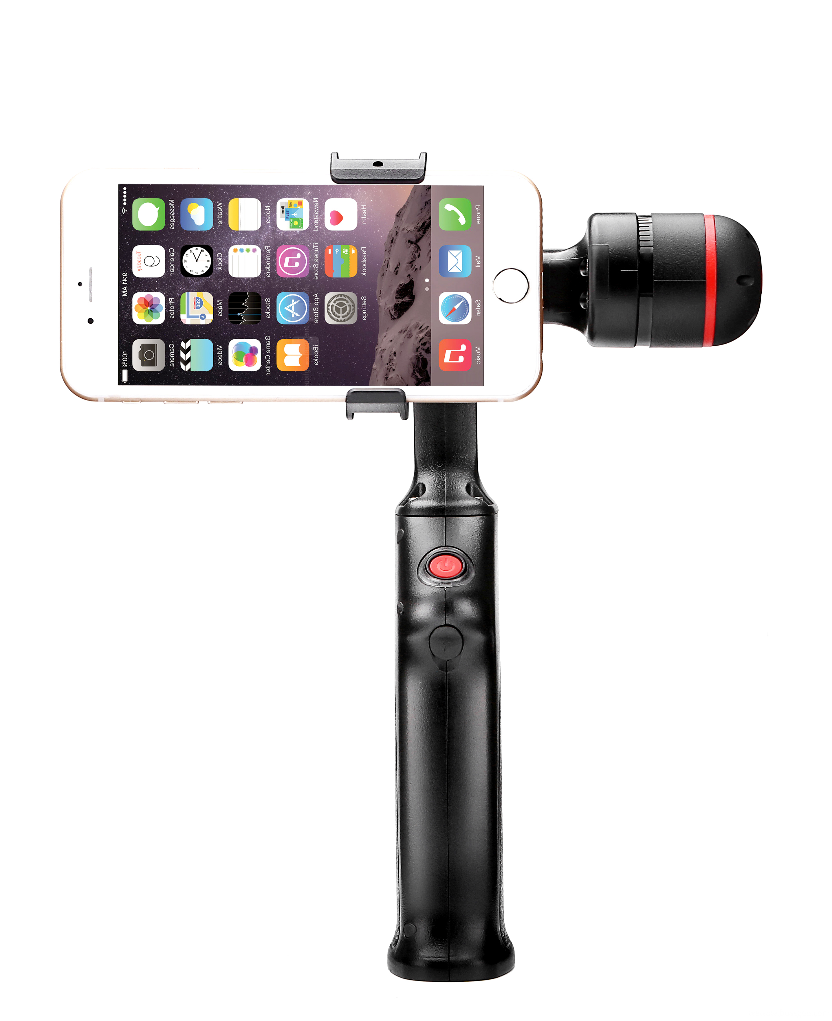
Two-axis phone stabilizer is composed of rolling axis and tilt-axis. With a gyro-stabilized gimbal system, it reduces the movements when you are moving to shoot a smooth video.

2 axis gimbal stabilizer is compatible with various smartphone.
Wewow focusing on handheld stabilizer is a technology company which does R & D independently. With Wenpod series product released, the company achieved the industry's praise and quickly became the leader of the smart stabilizer industry.
Our service
1. Reply to you within 24 hours.
2. Already sample: within 1-2days.
3. Shipping date: within 24 hours once get the payment.
4. 12 months warranty.
5. After-sales service, solve within 3 working dates.
If you have any questions, please contact with us directly.
Wewow appreciates domestic and international business relationship!
Two-axis Smartphone Stabilizer
Two-Axis Smartphone Stabilizer,Popular Two-Axis Smartphone Stabilizer,Professional Two-Axis Smartphone Stabilizer,Handheld Two-Axis Smartphone Stabilizer
GUANGZHOU WEWOW ELECTRONIC CO., LTD. , https://www.stabilizers.pl