Due to higher integration, faster processor speeds, and smaller feature sizes, core and I/O voltage point-of-load (POL) processor power supply designs are becoming more challenging. The development of processor technology must match the POL power supply design technology. For today's high-performance processors, power management solutions used five or ten years ago may no longer be effective. Therefore, when designing a POL power solution for Texas Instruments' DaVinci digital signal processor (DSP), a thorough understanding of basic power technology can help overcome many design challenges. This article takes a power management reference design based on TI power management products as an example to discuss a series of power supply decoupling, inrush current, voltage regulation accuracy and sequencing techniques for DaVinci processors.
This article refers to the address: http://
Large bypass decoupling capacitor
In addition to the full current used by the processor, the processor bypass and large capacitors of some power supplies are also important sources. When the processor's level of activity changes drastically and a steep load transient occurs, the local bypass capacitor is first provided with an instantaneous current, typically a small ceramic capacitor that responds quickly to load changes. As processing speeds increase, the need for more energy storage bypass capacitors becomes more important. Another source of energy is the large capacitance of the power supply. To avoid stability issues, make sure that the power supply is stable and that it can be properly started with the added bypass capacitor. Therefore, the power feedback loop must be compensated to accommodate additional bypass capacitors. The Power Evaluation Board (EVM) can be very effective on the test bench, but its performance may vary with many bypass capacitors added near the load.
As a rule of thumb, DaVinci power supplies can be placed by placing multiple 0603 or 0402 capacitors as close as possible to the processor's power supply pins (60 for core voltage and 30 for DM6?43 I/O voltage) The system noise of the voltage is completely decoupled. A smaller 0402 capacitor is a better choice because of its smaller parasitic inductance. Smaller capacitor values ​​(such as 560pF) should be closest to the power supply pin and the distance is only 1.25cm. Second, the closest to the power supply pin is a medium bypass capacitor (such as 220nF). TI recommends using at least 8 small capacitors and 8 medium capacitors per power supply and should be mounted next to the BGA via (occupying internal BGA space, or at least at external corners). Further a little larger, you can install larger, larger capacitors, but as close as possible to the processor [1].
Inrush current
A power supply with a large bypass capacitor has a startup problem because the power supply may not be able to charge the bypass capacitor, which is what is required to meet the processor requirements during startup. Therefore, during startup, an overcurrent may cause the power to turn off, or the voltage may temporarily drop (become non-monotonic). A good design practice is to ensure that the voltage does not drop during overshoot, overshoot or withstand high voltage for extended periods of time. To reduce the inrush current, the bypass capacitor can be slowly charged by increasing the startup time of the core voltage supply. Many DC/DC regulators have unique adjustable soft-start pins to extend voltage ramp time. If the regulator does not have such a soft-start pin, it can be implemented externally using an external MOSFET and an RC charging scheme.
This article recommends using a DC/DC regulator with current limit to help maintain a monotonic voltage ramp. The soft start scheme helps to meet the sequencing requirements of the DaVinci processor.
Power sequencing
More and more processor vendors offer recommended timing guidelines for core and I/O power-up sequencing. Once the timing requirements are known, the POL power supply designer can choose an appropriate technology. There are many ways to power on and off a dual power supply, with sequential sequencing and simultaneous sequencing being the most common.
When a short millisecond interval is required between the core and I/O power-up, sequential ordering can be implemented in any order. One way to implement sequential sequencing is to simply connect the PWERGOOD pin of one regulator to the ENABLE pin of another regulator. When the core and I/O voltage difference needs to be minimized during power-up and power-down, simultaneous sequencing is required. To perform simultaneous sequencing, the core and I/O voltages should be closely tracked to each other until a lower ideal voltage level is reached. In addition, the lower core voltage reaches its set point requirement, and the higher I/O voltage can continue to rise to its set value [2].
In self-boost mode, the DaVinci processor requires simultaneous sequencing of the CVDD and CVDDDSP core supplies. In master boost mode, CVDD must ramp up and reach its set value (1.2V) before the CVDDSP begins ramping up. As a maximum, the CVDDDSP supply must be powered up before the short-circuit switch between the "always on" and DSP domains is turned off (on). The I/O power supply (DVDD18, DVDDR2, and DVDD33) can be started in any order, but must be set to the set value [3] while the CVDD power supply is 100ms.
Voltage regulation accuracy
There are several factors that affect the voltage tolerance of a power system. Voltage reference accuracy is the most important factor and can be found in the product specification of the power management device. New regulators require ±1% accuracy or higher temperature reference accuracy. Some lower cost regulators may require ±2% or ±3% reference voltage accuracy. Please check the specifications of the regulator manufacturer in the product manual to ensure that the voltage regulation accuracy can meet the requirements of the processor. Another factor that affects the regulation accuracy is the tolerance of the external feedback resistor of the regulator.
A ±1% tolerance resistor is recommended when accurate tolerance values ​​are required. In addition, when this resistor is used to program the output voltage, it will bring an additional tolerance of ±0.5%. The specific calculation formula is: output voltage accuracy = 2*(1-VREF/VOUT)*TOLRES
The third influencing factor is the output ripple voltage. An excellent design practice is designed for peak-to-peak output voltages below 1% of the output voltage, which increases the voltage tolerance of the power system by ±0.5%. Assuming a baseline accuracy of ±2%, these three influencing factors add up to a power system accuracy of ±3%.
The DaVinci CVDD supply requires a 1.2V typical core supply that provides ±4.2% accuracy and 50mV tolerance. The 3.3V DVDD power supply has a tolerance of ±4.5% accuracy and 150mV, while the 1.8V DVDD power supply has a tolerance of ±5% accuracy and 90mV. It is important to keep the regulator close to the load to reduce path loss. It should be noted that if the power supply has a tolerance of 3% and the processor core voltage requires a 4.2% tolerance, the decoupling network must be designed to achieve 1.2% accuracy or 14mV capacity of the 1.2V rail [4]. difference.
Historical experience data shows that the core voltage is decreasing as processing technology develops. A slight change in the core voltage can provide higher performance or save more power. Choosing a regulator with a programmable output voltage and an output voltage tolerance of ±3% is a good design approach. Simple resistor changes or pin reconfigurations are much easier than redesigning a completely new power supply from scratch. Therefore, it is best to choose a regulator that can support output voltages as low as 0.9V or lower for maximum reuse and to help simplify the use of future versions of TI System-on-Chip (SoC) devices.
Reference design
We built several power management reference designs and tested them for digital audio/video applications. These designs use TI's TMS320DM6?43 and TMS320DM6?46 processors to meet sequencing, voltage accuracy and startup requirements. Figure 1 is a reference design circuit diagram of a 12V power supply. The design uses the TPS62111 synchronous buck converter, the TPS62040 synchronous buck converter, and the TPS73618 low-dropout regulator, which provide 3.3V, 1.2V, and 1.8V rails, respectively. This reference design includes a simple external MOSFET, resistor, and capacitor delay circuit to allow the 3.3V rail to meet the self-boost mode sequencing scheme. The TPS62040 not only provides a 1.2V core voltage, but also meets the sequencing requirements for Pin 5 soft-start capacitors. This solution has a tolerance of ±3% and an efficiency of over 90%. To meet the host boost mode sequencing scheme, a similar MOSFET, resistor, and capacitor circuit can be added to the 1.2V rail.
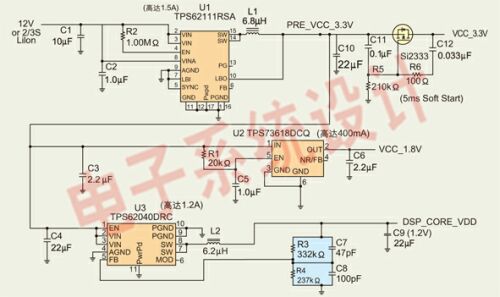
Figure 1:12V power supply reference design circuit diagram.
Figure 2 is a reset circuit. The circuit uses the TPS3808 and TPS3803 supply voltage monitors to monitor voltage rail changes. Please use the minimum TPS3808G01 (U5) to design the reset circuit power. If more than 3.3V rail/1.5A current and 1.2V rail/1.2A current are required, the TPS54350 and TPS54110S WIFT DC/DC converters may be used to achieve 3A and 1.5A currents, respectively. The SWIFT regulator features digital video EVM based on DaVinci technology. For more information on 5V and 12V input power supplies using linear regulators, TPS40K DC/DC converters, TPS62xxx DC/DC converters or multiple output power management units (PMUs)
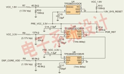
Figure 2: Rail voltage reset and voltage monitoring circuit.
Summary of this article
Once you fully understand the decoupling, sequencing, and tolerance requirements, it is very straightforward to design a power solution for your DaVinci processor. Sticking to the above techniques is a pretty good design practice when designing power supplies for all high-performance processors. If additional support is needed, some reference designs can be obtained from TI to speed up the time to market.
Steel Roof Tile Roll Forming Machine
Tile Roll Forming Machine,Roof Tile Making Machinehine,Metal Tile Roll Forming Machine,Roofing Sheet Making Machine
Haoshuo Technology Co., Ltd. , http://www.whrollformingmachine.com