1 Antenna
1.1 The role and status of the antenna The power of the radio frequency signal output by the radio transmitter is transmitted to the antenna through the feeder (cable), and the antenna radiates it in the form of electromagnetic waves. After the electromagnetic wave arrives at the receiving location, it is followed by the antenna (receiving only a very small part of the power) and sent to the radio receiver through the feeder. It can be seen that the antenna is an important radio device that emits and receives electromagnetic waves. Without an antenna, there is no radio communication. There are many types of antennas for different frequencies, different uses, different occasions, different requirements, etc. For many types of antennas, proper classification is necessary: ​​according to usage, it can be divided into communication antennas, TV antennas, radar antennas, etc .; according to the working frequency band, it can be divided into short-wave antennas, ultra-short wave antennas, microwave antennas, etc. Directional classification can be divided into omnidirectional antennas, directional antennas, etc .; according to shape classification, it can be divided into linear antennas, planar antennas, etc .; and so on.
* Electromagnetic wave radiation When an alternating current flows on the wire, electromagnetic wave radiation can occur. The ability to radiate is related to the length and shape of the wire. As shown in Figure 1.1 a, if the distance between the two wires is very close, the electric field is bound between the two wires, so the radiation is very weak; open the two wires, as shown in Figure 1.1 b, the electric field is spread in the surrounding space, so Radiation enhancement. It must be pointed out that when the length L of the wire is much smaller than the wavelength λ, the radiation is very weak; when the length L of the wire is increased to be comparable to the wavelength, the current on the wire will be greatly increased, so that stronger radiation can be formed. 
1.2 Symmetrical vibrator Symmetrical vibrator is a classic and most widely used antenna to date. A single half-wave symmetrical vibrator can be used simply or independently as a feed for a parabolic antenna, or multiple half-wave symmetrical vibrators can be used to form an antenna Formation. Oscillators with equal lengths of both arms are called symmetrical oscillators. A vibrator with a quarter-wavelength per arm and a half-wavelength full-length is called a half-wave symmetrical vibrator, see Figure 1.2a. In addition, there is a special-shaped half-wave symmetrical vibrator, which can be regarded as a full-wave symmetrical vibrator folded into a narrow rectangular frame, and the two end points of the full-wave symmetrical vibrator are overlapped. This narrow long rectangular frame is called Reducing the dipole, note that the length of the dipole is also half the wavelength, so it is called a half-wave dipole, see Figure 1.2b. 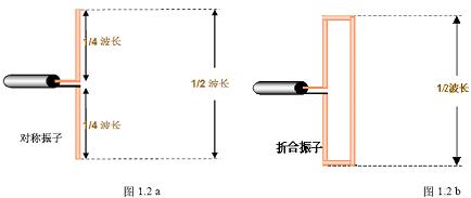
1.3 Discussion of antenna directivity
1.3.1 Antenna directivity One of the basic functions of the transmitting antenna is to radiate the energy obtained from the feeder to the surrounding space, and the second basic function is to radiate most of the energy in the desired direction. Vertically placed half-wave symmetrical oscillators have a flat “doughnut†-shaped stereo pattern (Figure 1.3.1 a). Although the three-dimensional pattern is strong in three-dimensional sense, it is difficult to draw. Figure 1.3.1 b and Figure 1.3.1 c show its two main plane patterns. The plane pattern describes the directivity of the antenna on a specified plane. As can be seen from Figure 1.3.1 b, the radiation is zero in the direction of the axis of the vibrator, and the maximum radiation direction is on the horizontal plane; while from Figure 1.3.1 c, it can be seen that the radiation in the various directions on the horizontal plane is as large. 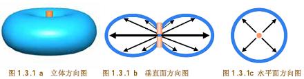
1.3.2 Enhancement of antenna directivity Several symmetrical vibrator arrays can control the radiation, generate a "flat donut", and further concentrate the signal in the horizontal direction.
The figure below is a stereo directional diagram and a vertical directional diagram when four half-wave oscillators are arranged vertically along a vertical line into a vertical quaternion array. 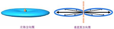
The reflection plate can also be used to control the radiant energy to one side, and the plane reflection plate is placed on one side of the array to form a sector-shaped area to cover the antenna. The following horizontal plane diagram illustrates the role of the reflecting surface --- the reflecting surface reflects the power in one direction, which improves the gain. 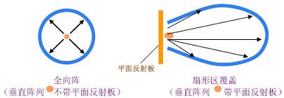
The use of a parabolic reflective surface can make the radiation of the antenna, like the searchlight in optics, concentrate the energy into a small solid angle, thereby obtaining a high gain. It goes without saying that the composition of a parabolic antenna includes two basic elements: a parabolic reflective surface and a radiation source placed on the focal point of the parabolic surface.
1.3.3 Gain Gain refers to the ratio of the power density of the signal generated by the actual antenna and the ideal radiating element at the same point in space under the condition of equal input power. It quantitatively describes the degree to which an antenna radiates concentrated input power. The gain is obviously closely related to the antenna pattern. The narrower the main lobe of the pattern, the smaller the side lobe and the higher the gain. The physical meaning of gain can be understood in this way --- to produce a signal of a certain size at a certain point at a certain distance, if an ideal non-directional point source is used as the transmitting antenna, 100W of input power is required, and When a directional antenna with a gain of G = 13 dB = 20 is used as the transmitting antenna, the input power is only 100/20 = 5W. In other words, the gain of an antenna, in terms of its radiation effect in the direction of maximum radiation, is a multiple of the amplification of the input power compared to an ideal point source with no directivity.
The gain of the half-wave symmetrical oscillator is G = 2.15dBi.
The four half-wave symmetrical oscillators are arranged up and down along the vertical line to form a vertical quaternion array with a gain of about G = 8.15dBi (the unit of dBi means that the comparison object is an ideal point source with uniform radiation in all directions).
If a half-wave symmetrical oscillator is used as a comparison object, the unit of its gain is dBd.
The gain of the half-wave symmetrical oscillator is G = 0dBd (because it is compared with itself, the ratio is 1, and the logarithm is zero.) For a vertical quaternion array, the gain is about G = 8.15–2.15 = 6dBd.
1.3.4 Lobe width The directional pattern usually has two or more lobes. The lobe with the largest radiation intensity is called the main lobe, and the remaining lobes are called side lobes or side lobes. See Figure 1.3.4 a. On both sides of the maximum radiation direction of the main lobe, the angle between two points where the radiation intensity is reduced by 3 dB (power density is reduced by half) is defined as the lobe width (also known as the beam width or the main lobe width or half Power angle). The narrower the lobe width, the better the directivity, the farther the distance, and the stronger the anti-interference ability. 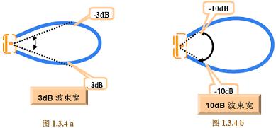
There is also a lobe width, that is, a 10dB lobe width, which, as the name implies, is the angle between two points where the radiation intensity in the pattern is reduced by 10dB (the power density is reduced to one-tenth), see Figure 1.3.4b.
1.3.5 Front-to-back ratio In the direction diagram, the ratio of the maximum value of the front and back lobes is called the front-to-back ratio, and is denoted as F / B. The larger the front-to-back ratio, the smaller the backward radiation (or reception) of the antenna. The calculation of the front / back ratio F / B is very simple ------
F / B = 10 Lg {(forward power density) / (backward power density)}
When the front-to-back ratio F / B of the antenna is required, its typical value is (18 ~ 30) dB, and in special cases it is required to reach (35 ~ 40) dB. 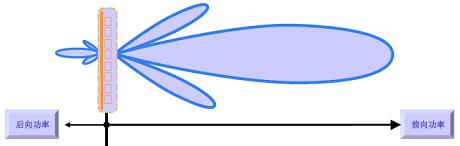
1.3.6 Some approximate calculation formulas of antenna gain
1) The narrower the antenna main lobe width, the higher the gain. For general antennas, the gain can be estimated using the following formula:
G (dBi) = 10 Lg {32000 / (203dB, E × 203dB, H)}
In the formula, 203dB, E and 203dB, H are the lobe width of the antenna on the two principal planes;
32000 is statistical empirical data.
2) For a parabolic antenna, the gain can be approximated by the following formula:
G (dB i) = 10 Lg {4.5 × (D / λ0) 2}
In the formula, D is the diameter of the paraboloid;
λ0 is the central working wavelength;
4.5 is the statistical empirical data.
3) For the upright omnidirectional antenna, there is an approximate calculation formula
G (dBi) = 10 Lg {2 L / λ0}
In the formula, L is the antenna length;
λ0 is the central working wavelength;
1.3.7 Upper side lobe suppression For a base station antenna, people often require that the first side lobe above the main lobe is as weak as possible in its vertical (ie, pitch) direction pattern. This is called upper side lobe suppression. The base station serves the mobile phone users on the ground, and the radiation pointing to the sky is meaningless. 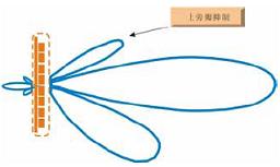
1.3.8 Downtilt of the antenna To make the main lobe point to the ground, the antenna needs to be tilted down moderately.
Powerbanks are popular for charging smartphones and mobile tablet devices. A powerbank is a portable device that can supply power from its built-in batteries through a USB port. They usually recharge with USB power supply. Technically, a powerbank consists of rechargeable Lithium-ion or Lithium-Polymer batteries installed in a protective casing, guided by a printed circuit board (PCB) which provides various protective and safety measures. Due to its general purpose, powerbanks are also gaining popularity as a branding and promotional tool. Different brands and promotional companies use it as a promotional tool and provide a customized product.
Specifications:
Capacity in mAh: mAh stands for milli Ampere-hour and measures the amount of power flow that can be supplied by a certain powerbank at a specific voltage. Many manufacturers rate their products at 3.7 V, the voltage of cell(s) inside. Since USB outputs at 5 V, calculations at this voltage will yield a lower mAh number. For example, a battery pack advertised with a 3000 mAh capacity (at 3.7 V) will produce 2220 mAh at 5 V. Power losses due to efficiency of the charging circuitry also occur.
Simultaneous charging and discharging: need to specify if the powerbank can be used while it is charging.
Number of output USB ports: This specifies the number of devices that can be charged simultaneously.
Output current rating: This specifies the current rating that it can charge maximum. The higher the number, the better the powerbank. This can vary from output port to output port.
Input Current Rating: Input current rating is the amount of current the powerbank is able to draw at its maximum level while getting charged.
Safety Protections: Over Voltage Protection, Over Charge Protections, Over Current Protections, Over Heat Protections, Short-Circuit Protections and Over Discharge Protections are the common safety measures observed with standard powerbanks.
LED Indications: The Led glows as per indicating the amount of charging ability left with the powerbank.
USB Power Bank,Custom PVC Power Bank,Power Bank Charger,Power Bank Portable Charger
Custom Usb Gift company limited , https://www.customusbgift.com