Research on Multi-Pulse Combination Modulation UWB Communication Performance
0 Introduction The main feature of ultra-wideband technology is that its system structure is relatively simple to implement, and device integration is simplified; high-speed data transmission, UWB exchanges high-speed data transmission at a very wide frequency, and the transmission rate can be in the range of 10 m. Reaching 500 Mb / s, it is an ideal modulation technology for personal communication and wireless LAN.
UWB modulation and multiple access methods are one of the key technologies. The choice of modulation scheme affects the structure of signal power spectral density, such as traditional modulation methods: TH-PPM, TH-BPSK, DS-BPSK, etc. In this paper, based on the study of multi-pulse position modulation in literature [2], the pulse signal is added Modulation, using extended equal weight code (ECWC) to construct a UWB time-hopping modulation scheme called bipolar multi-pulse position modulation (MPPPM), and designed its signal construction and modulation, and its communication performance Analysis and comparison.
1 MPPPM signal model
1.1 The signal form MPPPM is a multi-pulse combination modulation, it is the generalization of ordinary single pulse PPM and multi-pulse PPM, allows multiple pulses per symbol interval, it uses the position and polarity of multiple pulses in the symbol slot frame Different combinations of information transfer information, each pulse can change its slot position and polarity.
The L-dimensional MPPPM ultra-wideband time-hopping signal can be described as multiple pulses placed into L time slots, the interval within a symbol time is Ts = Nb × L × Tm, then Nh is the time of each signal symbol. The number of bit repetitions, Tm is the time interval of the impulse response. Obviously, put ω (l <ω
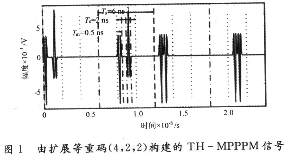
The modulation signal adopts secondary repetition coding, which respectively represents (-1 0 + 1 0) and (0-1-1 0) two codewords.
1.2 Signal communication system structure Figure 2 shows the UWB signal transmission scheme in TH-WUB combining multi-ary PPM and BPSK.
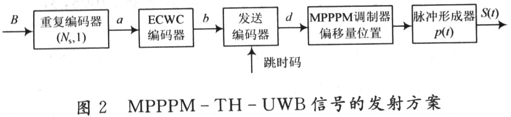
Combined with this model, the process of generating and receiving UWB signals during MPPPM hopping is as follows: given the L to be transmitted (assuming L = 2wCwn) hexadecimal sequence B = (..., B0, B1 ..., Bi ...), the rate is RB = 1 / TB. The repeating encoder module in Figure 2 repeats each bit Ns times, producing a new L-ary sequence B = (..., a0, a1, ..., ai, ...), and the new baud rate Ra = Ns / TB = 1 / Ts. This process belongs to channel coding, and introducing redundancy helps reduce the bit error rate at the receiving end. The new sequence a enters the ECWC encoder of the second module. The sequence a is mapped to the ECWC code to generate the ECWC sequence b = (..., b0, b1, ..., bi, ...), where bi is the extended equal weight code C (n, d, w) the corresponding codeword. The mapping signal b generates a new sequence d by sending the encoder and applying the time-hopping code sequence c = (..., C0, C1, ..., Cj, ...). The general elements of the sequence d can be expressed as:

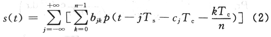
Where: bjk is the k-th element in the J-th extended equal-weight codeword; cj is the j-th element in the sequence c, and c is usually a pseudo-random sequence, which is the time-hopping code assigned to the user. The above process implements code division multiple access coding and has an impact on the frequency spectrum of the transmitted signal. The fourth module entered by sequence d is the MPPPM modulation module, which generates a unit pulse sequence, and these pulses are modulated to the position on the time axis at jTs + djk (0≤k≤n-1). Among them, Ts is the symbol time. The last module before the channel is a pulse forming filter with impulse response P (t) to ensure that the output sequence does not overlap. The signal sent by the system before the channel is:
2 MPPPM signal data rate and bit error rate under AWGN channel
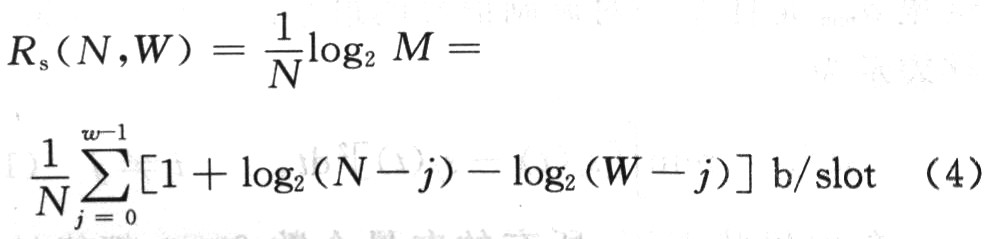
2.1 Signal data rate under ideal channel The characteristics of MPPPM can be expressed as W pulse vectors under N time slots, the value of the vector is +1 or -1, and 0 in the remaining N-W time slots. The number that this vector can represent is: 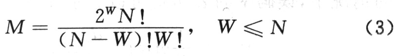
Therefore, the data rate represented in each time slot is:
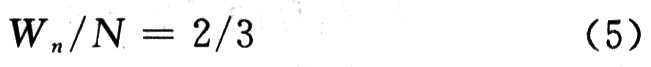
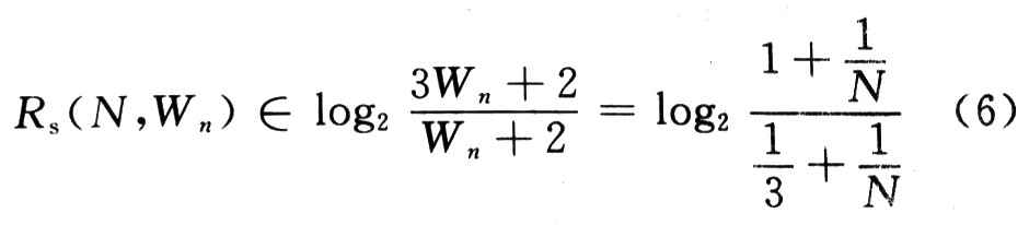
From [4], the relationship between N and W at the maximum data rate is:
2. 2 MPPPM bit error rate under AWGN channel In order to simplify the analysis, it is assumed that the system has only one user at a time, and the Gaussian white noise channel is a signal interference. Assuming Tc / n ≥ Tm, this can avoid the overlap between adjacent pulses, so that each pulse meets the orthogonality of the signal, based on the above assumptions to study the bit error rate of the MPPPM signal.
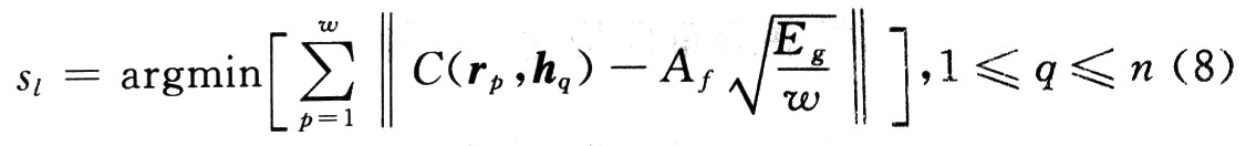
Suppose hq (1≤q≤n) represents the qth basic signal vector, the expression is [0,0, ..., 1, ... 0], where 1 is in the qth dimension of the vector, assuming the transmitted signal is Sl, receive The machine makes the judgment based on the minimum Euclidean distance between the signals;

Assuming that the number of pulse repetitions is 1, the demodulated signal is:
According to the method in [8, 9], the error rate of MPPPM is deduced:
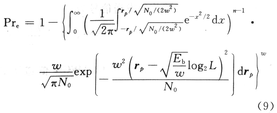
Since the error rate expression of equation (9) is very complicated, the upper limit expression of the error rate is derived below. The shortest Euclidean distance between the two signals is the main factor that causes the bit error rate. When the signal-to-noise ratio is high, the expression of the bit error rate can be expressed as follows:
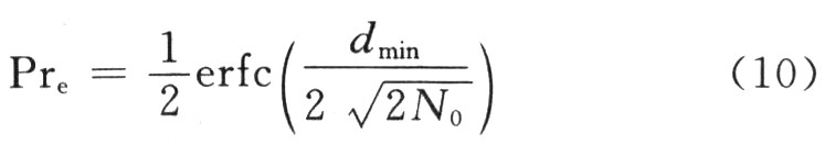
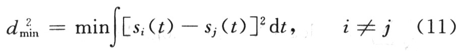
Here dmin is the minimum Euclidean distance of any pair of modulated signals, which can be expressed as:
In an ideal state, all vector numbers 2wCwn can be used, but due to the relationship between the minimum Hamming distance and a lower bit error rate, the larger the minimum Hamming distance, the lower the bit error rate of the signal, which can only be selected Some vectors with larger Hamming distance are used. In this case, the minimum Euclidean distance of MPPPM is expressed as:
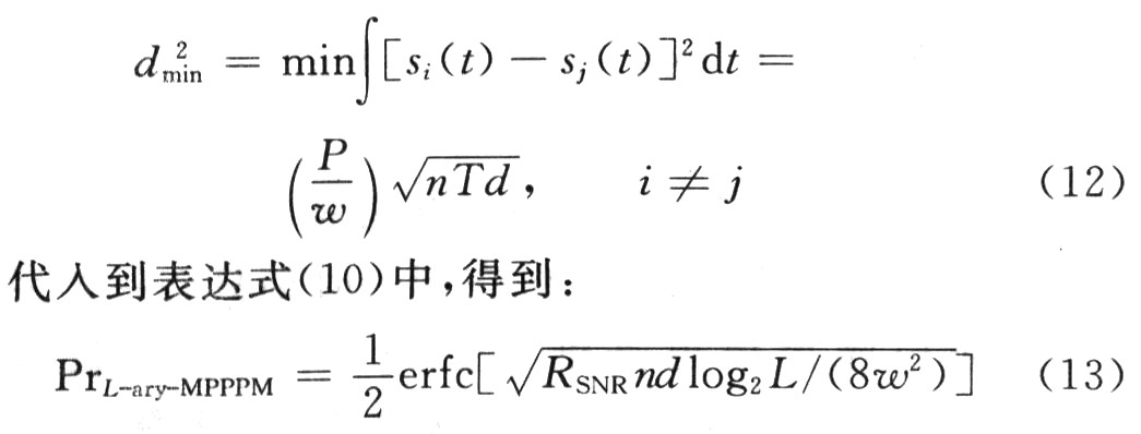
In the formula; n, w are the parameters of the extended equal weight code used to construct the L-ary MPPPM; n is the dimension of the transmitted and received signal vector; w is the number of pulses used.
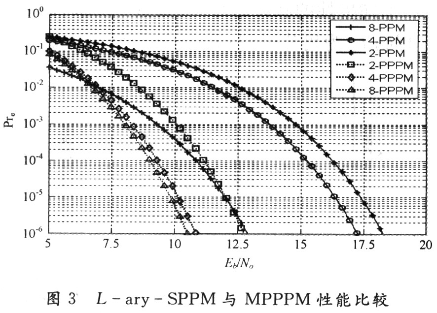
3 Numerical comparison results L-ary-SPPM, MPPPM bit error rate with the signal-to-noise ratio curve shown in Figure 3, the simulation parameters are set to L = [2, 4, 8], n = [2, 2, 3], w = 2. It can be seen from the figure that the performance of L-ary SPPM and L-ary MPPPM has been improved. In addition, the bit error rate of L-ary MPPPM is lower than the corresponding L-ary PPM, and the performance of only 2 PPlc'M is worse than that of 8 SPPM.
4 Conclusion This paper uses extended equal weight codes to construct a UWB time-hopping modulation scheme called bipolar multi-pulse position modulation (MPPPM), and analyzes and compares its communication performance. The results show that under certain conditions, MPPPM modulation technology can achieve better performance than multi-pulse position modulation and single-pulse multi-position modulation with higher data rate and lower bit error rate.
Solar LED land lamp uses sunlight as the energy source, charges during the day and uses at night, does not need complex and expensive pipeline laying, can arbitrarily adjust the layout of lamps and lanterns, safe and energy-saving, pollution-free, stable and reliable without manual operation, saving electricity and maintenance. Solar LED street lamp is mainly composed of solar cell module (including bracket), LED lamp holder, control box (with controller, battery) and lamp pole.
Solar Led Street Light,Street Light Lamp,Solar Powered Street Lights,Solar Powered Led Street Lights
Yangzhou Heli Photoelectric Co., Ltd. , https://www.heli-eee.com