VLAN and its application analysis in campus network
1 Introduction
VLAN (Virtual Local Area Network), also known as virtual local area network, is built on the basis of LAN switches and is an end-to-end logical network that can be built across network segments and different networks using network management software. A VLAN forms a logical subnet, that is, a logical broadcast domain, which can cover multiple network devices, allowing network users in different geographic locations to join a logical subnet, which is basically the same in function and operation as a traditional LAN Interconnection of terminal systems within a certain range.
2 Features of virtual local area network technology
Compared with the ordinary campus network, the campus network based on VLAN has the following characteristics:
(1) The addition, movement and other changes of simple management nodes are handled quickly and conveniently through the management console, without the need to go to the wiring room for adjustment.
(2) Performance improvement By limiting the node-to-node communication and broadcast communication of the entire network, the virtual subnet can save bandwidth and thereby reduce costs.
(3) Good network security Virtual subnets create virtual boundaries, which can only be crossed by routers, so standard security measures based on routers can be used to restrict access to each virtual subnet when needed.
3 VLAN division method
3.1 VLAN based on port division
The VLAN is divided according to the standard of the specific VLAN to which the port of the network device belongs. For example, in an 8-port bridge, ports 1, 2, 4, and 7 belong to VLAN 1. Ports 3, 5, 6, and 8 belong to VLAN 2. The devices connected to these ports and the data frames sent and received by them also belong to VLAN1 and VLAN2, respectively. The advantage of this division method is that it is very simple to define VLAN members, and all the ports can be specified; the disadvantage is that it does not allow users to move around casually. If a user belonging to a VLAN leaves the original port and reaches a port of a new network device, the network administrator must redefine the VLAN.
3.2 Divide VLAN based on MAC address
Divide the VLAN by the MAC address of the computer workstation network card. The biggest advantage of this division method is that because a MAC address uniquely corresponds to a computer network card, when the physical location of a computer workstation changes, that is, when it is transferred from one switch to another switch, there is no need to reconfigure the VLAN.
3.3 Divide VLAN based on network layer protocol type
If the network supports multiple network layer protocols, VLANs can also be divided according to the network layer protocol type field in the data frame header, which is very important for network managers. At the same time, this method does not require additional frame tags to identify VLANs, which can reduce the network Traffic.
3.4 Divide VLAN based on network layer subnet address
VLANs are divided according to the network layer subnet address in the data packet header. Although this division method is based on layer 3 information, that is, network addresses (such as IP addresses), it has nothing to do with the routing function of the network layer. It just looks at the network layer address of each data packet. And according to the pre-defined information in the filtering database, decide which VLAN it belongs to, and then perform bridge exchange according to the spanning tree algorithm, which does not involve any routing operation. The advantage of this method is that when the physical location of a computer workstation changes, it is transferred from one switch to other switches. No need to reconfigure VLAN. However, its disadvantage is its low efficiency, because it is time-consuming to check the network layer address of each data packet relative to the implementation technology of VLANs 1 and 2. Generally, the switch chip has more flexibility, and it is also easy to expand through the router; but its disadvantage is that it is not suitable for LAN and has low efficiency.
4 Communication between VLANs
When using a router to implement inter-VLAN communication, there are two ways to connect the router to the switch. The first is to connect to each VLAN on the switch through different physical interfaces of the router; the second is to connect to each VLAN of the switch through the logical sub-interface of the router. The dedicated VALN divides ports into three types: promiscuous ports, isolated ports, and group ports. Only promiscuous ports can be connected to routers or Layer 3 switches. The VLAN corresponding to the promiscuous port is called a primary VLAN, and it can communicate with all the isolated VLAN (Isolated VLAN) ports and community VLAN (Community VLAN) ports mapped to the promiscuous port. In addition to communication with the Primary VLAN, the ports of the Community VLAN can also communicate with each other within the internal ports. The ports in the isolated VLAN can only communicate with the ports of the Primary VLAN, and the internal ports are isolated from each other. The realization of mutual communication between different VLANs is given below.
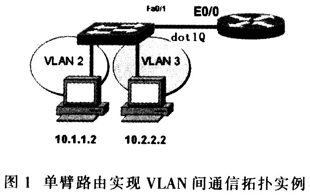
4.1 One-arm router connects to virtual LAN
VLANs are divided in the campus internal network. When some hosts need to communicate between VLANs, the switch does not support Layer 3 switching. At this time, a router that supports 802.1Q can be used to implement VLAN interworking. Just establish a sub-interface on the Ethernet port, assign an IP address as the gateway of the VLAN, and start the 802.10 protocol.
As shown in Figure 1, a single-arm router refers to the use of one port of the router to connect multiple VLANs. The implementation method is to configure multiple logical sub-interfaces. The router and the switch are connected by an external line, and there is only one external line. However, it is logically separated, and the data packets that need to be routed reach the router through this line, and then return to the switch through this line for forwarding after routing. therefore. This topology is called one-arm routing, that is, when a packet enters a certain port, it comes out of that port.
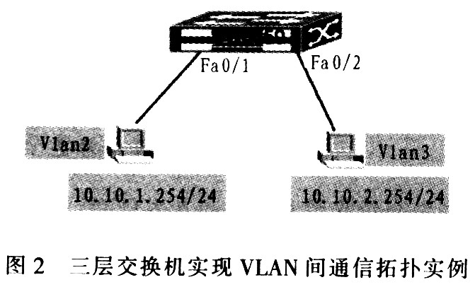
4.2 Use three-layer switch to realize host communication between different VLANs
A Layer 3 switch is essentially a Layer 2 switch with routing functions. Layer 3 switches combine the advantages of both layer 2 switches and layer 3 routers organically and intelligently to provide wire-speed performance at all levels. This integrated structure also introduces strategic management attributes. In a three-layer switch, the switch module and the router module are set separately; and the built-in routing module is similar to the switching module, and also uses ASIC hardware to handle routing. The specific configuration is shown in the example of Layer 3 switch to achieve the inter-VLAN communication topology.
The specific configuration of SW3550 is as follows:
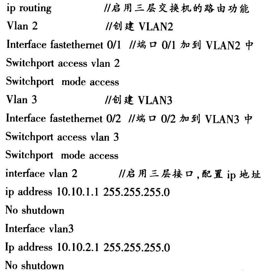
The gateways of other VLAN2 and VLAN3 hosts point to 10.10.1.1.10.10.2.1.
5 Conclusion
As a new type of network technology, VLAN can provide a good method for solving the problems of flexible configuration and network security of network sites. Although VLAN technology still has problems such as the unification of technical standards, the overhead of VLAN management and the automation of VALN configuration, etc., with the advancement of technology. These problems will be gradually solved, and VLAN technology is widely used in network construction, thereby playing a greater role in improving the working efficiency of the network. With the continuous expansion and development of the campus network, the VLAN technology is also more widely used in the campus network.
Rectifier Diode(Standard Diode) utilizes the unidirectional conductivity of the diode, which can convert the alternating current of alternating direction to a pulsating direct current of a single direction. Rectifier diode – diode designed for rectifying alternating current (mostly with low power frequency – 50 Hz at high power emitted during load). The main task of the rectifier diode is to convert AC voltage into DC voltage through application in rectifier bridges. The variant of rectifier diodewith the Schottky barrier is particularly valued in digital electronics.
")
Rectifier Diode(Standard Diode)
Rectifier Diode,Standard Diode,High Power Rectifier Diode,High Voltage Rectifier Diode
YANGZHOU POSITIONING TECH CO., LTD. , https://www.yzpst.com