Design and function of voice-controlled quasi-duplex wireless intercom
The wireless walkie-talkie introduced in this article is a FM quasi-duplex mode. The operating frequency is 30MHz. It uses voice-activated electronic switches. It is convenient, energy-saving, and simple in circuit. The operating voltage is 3-9V, and the transmission power is 1-5W.
Working principle The receiving and transmitting of the wireless interphone are divided into two relatively independent parts, and only the antenna matching network is shared by transmitting and receiving.
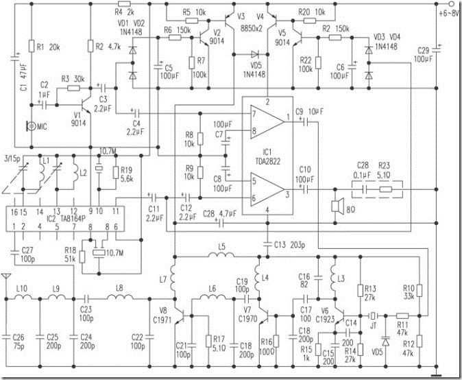
The transmitting part is composed of microphone amplifying circuit, electronic switch, power amplifying circuit, transmitting circuit and antenna matching network. When speaking, the voice is detected by the electret microphone MIC, amplified by the transistor V1, coupled out by C3, and divided into two channels. All the way through the voltage doubler rectifier circuit composed of D1, D2, C5 becomes a DC voltage to turn on the electronic switch composed of V2, V3 and its peripheral components, so that the audio power amplifier integrated circuit IC1 and V6, V7, V8 and its peripheral components The transmitting circuit of the receiver is powered up and works; the other route is coupled to IC1 for power amplification via C4, and then sent to the oscillation and frequency doubling circuit composed of transistor V6, varactor diode VD6 and crystal JT through C9 to become a 30MHz FM wave. Selected by L3 and C16, coupled to the Class C excitation stage composed of V7 and its peripheral components through C17 for excitation amplification, and then coupled to the Class C power amplifier circuit composed of V8 and its peripheral components through C19 for power amplification, after amplification After passing through the L8 and C23 series resonant circuit, the RF signal is transmitted out through the antenna matching network composed of C24 ~ C26 and L9 and L10.
The receiving part is composed of antenna matching network, FM receiving circuit, electronic switch and audio power amplifier circuit. The high frequency signal of about 30MHz received by the antenna is coupled by C27 to the FM receiving special integrated circuit TA8164P. After high-amplification, local oscillation, mixing, intermediate amplifier and frequency discrimination, the audio signal is output from the {11} pin of IC2. After C11, it is divided into two paths. All the way through the voltage doubler rectifier circuit composed of VD3, VD4, C6 becomes a DC voltage, to open the electronic switch composed of V4, V5 and its peripheral components, so that the power amplifier circuit IC1 is energized to work. The other route is coupled to IC1 by C12, and the audio signal after power amplification is coupled out by C10 to drive the speaker to sound.
VD5 in the picture is an isolation diode. Its function is to prevent the transmission circuit from being mistakenly turned on when the electronic switch composed of V4 and V5 is turned on, which plays the role of saving energy and protecting the transmission circuit.
R23 and C28 in the dotted frame in the figure are set to prevent self-excitation of the amplifier and howling of the horn. If the power amplifier is not self-excited and the speaker is not howling, it can be omitted.
Component selection V3, V4 can also use transistor 9012, V7 can also be used 3DA106A, V8 can also be used 3DA107A, JT selects a crystal with a frequency of 10MHz.
The transmission frequency is mainly determined by L3, C16 and L8, C23. In order to reduce the volume of the whole machine, all components, especially resistors and capacitors should be selected as small or ultra-small, and strictly selected.
Debugging method Adjust the transmitting part first, and then adjust the receiving part. First of all, close-up debugging, you can first fix the receiving part of one machine, fine-tune the transmitting part of another machine, fine-tune the frequency-sensitive components L3, C16 and L8, C23, so that a machine can receive voice, and then fine-tune the frequency of the receiving part Sensitive components L1, L2 and double adjustable capacitance make the sound clearest. For further long-distance debugging, a certain distance (1 to 2 kilometers) can be pulled away for more fine-tuning, so that the transmission and reception effects are optimal.

Dog Training System Accessories
Dog Training System,Shock Collar System,Sportdog Contain And Train,The Perfect Dog Training System
Elite-tek Electronics Ltd , https://www.aetertek.ca