Design of a data acquisition system based on CAN bus technology
1 Introduction In the marine environment, because the measurement site is far away from the shore and the environment is harsh, the measurement device must be separated from the computer system to form a remote data collection system. There are generally two data transmission methods for remote data acquisition systems: frequency transmission and serial communication. The frequency quantity has strong anti-interference ability, which is convenient for long-distance transmission, but this remote frequency measurement is generally only applicable to the lower frequency range below tens of hertz. In serial communication, the RS-232 communication standard data transmission rate is slow (usually the asynchronous communication rate is limited to 19.2kbps or less), the transmission distance is short (generally the cable length is 15m), and it is not suitable for remote data collection
System; RS-449, RS-422 and RS-423 and other communication standards, real-time is not strong; RS-485 can only constitute a master-slave structure system, the communication method can only be carried out by the polling of the master station, the system Real-time performance and reliability are poor; and when multiple nodes in the system send data to the bus at the same time, it will cause the bus to exhibit a short circuit, thereby damaging some nodes.
CAN (Controller Area Network) bus belongs to the field bus category, it is a serial communication network that effectively supports distributed control or real-time control. The CAN bus communication interface integrates the functions of the physical layer and data link layer of the CAN protocol, and can complete the framing processing of the communication data. One of the biggest features of the CAN protocol is the abolition of the traditional station address coding, and instead of encoding the communication data block. The advantage of using this method is that the number of nodes in the network is not limited in theory. The identification code of the data block can be composed of 11-bit or 29-bit binary numbers, so 211 or 229 different data blocks can be defined. According to the way of data block coding, different nodes can also receive the same data at the same time. The length of the data segment is 8 bytes, which will not occupy the bus for too long, thus ensuring the real-time nature of the communication. The CAN protocol adopts CRC check and can provide corresponding error handling functions to ensure the reliability of data communication.
2 System design The remote data acquisition system requires that the sensor and the measuring device are located at the measurement site, and the computer system is on the shore or on the ship. The distance between them is often several hundred meters, sometimes even several kilometers. Therefore, it is particularly important to have fewer connecting wires and lower maintenance costs. In this paper, the measurement system uses CAN to build a remote underwater data acquisition system for the magnetic field (3 components), electric field (3 components), and inclination parameters (2 components). It uses 3 measurement nodes to implement real-time real-time on the above 8 sensor signals. Collection and transmission. The block diagram of the remote underwater data acquisition system is shown in Figure 1.
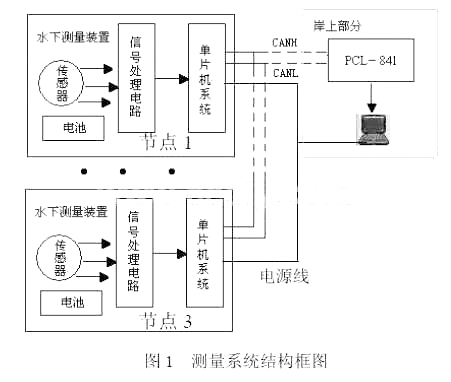
The remote data acquisition system is mainly composed of two parts: the shore receiving and processing part and the underwater measuring device. In order to prolong the service time of the battery, the on-off of the battery power of the underwater measuring body is controlled from the shore. The data acquisition system uses a four-core longitudinally sealed seawater cable, two channels to transmit data, and the other two to control battery power.
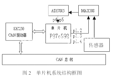
2.1 Hardware circuit design The sensor uses a magnetic field three-component measurement module, an electric field three-component measurement module, and an inclination 2-component measurement module. In the signal processing circuit, each signal is amplified and filtered. The amplification uses two LM148 four op amps. The filter is a cascade of two active low-pass filtering second-order nodes formed by an operational amplifier. The single-chip system sends a total of 8 signals of electric field three-component signal, magnetic field three-component signal and two attitude angle signals to A / D for conversion. A / D conversion uses 16-bit chip ADS7805 produced by BB company, and its input voltage The range is ± 10V, 16-bit and 8-bit output is optional. Here, 16-bit parallel output is used, and the control signal is generated by the port lines P1.0, P1.1 and P1.2 of the single-chip microcomputer. The block diagram of the single-chip microcomputer system is shown in Figure 2. As shown. What the one-chip computer adopts PHILIPS is the microcontroller P87C592 with CAN function again, the crystal frequency is 16MHz, P0 port and P2 port are used as the data line and address line, P4 port and P5 port are used as the 16-bit analog-to-digital converter Bits and lower 8-bit parallel data lines. P1.6, P1.7 are used for the CAN bus, and P1.2, P1.3, and P1.4 control the channel of the eight-choice multiplexer MAX308. PC82C250 is a CAN bus transceiver, which is the interface between the CAN controller and the physical bus, and provides the drive transmission capability to the bus, the differential transmission capability to the CAN controller, and the differential reception capability to the CAN controller. It has a strong ability to resist instantaneous interference and protect the bus; there are 3 different working modes namely high speed, slope control and standby. The power failure of a node on the bus will not affect the bus, and high-speed applications up to 1 Mbps can be achieved within 40 m. The receiving end of the host uses PCL-841. PCL-841 can be directly inserted into the ISA expansion slot of the computer. The computer assigns a memory address to PCL-841 and reads and writes it as standard memory. The memory address can be set to C800H through a jumper To any one of the 40 base addresses in EF00H. It is a CAN bus communication card with a built-in CAN controller, which provides bus arbitration and error detection and automatic retransmission functions, thereby avoiding data loss and ensuring the reliability of the system.
2.2 System software design To realize effective and real-time communication, software design is the key and difficult point. The software design of this system includes two parts, namely the single-chip computer program and the host computer control and data processing program.
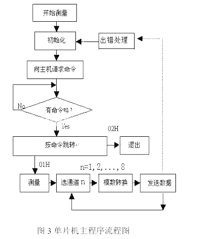
The single chip microcomputer program mainly includes the node initialization program, the message sending program, the message receiving program and the CAN bus error processing program. The flow chart of the main program of the single chip microcomputer is shown in Figure 3, and the program is written in C51 language.
The CAN controller appears to the CPU as a register image peripheral device that ensures that both parties work independently. The exchange of status, control and commands between the microcontroller and the CPU is through reading these registers in the reset mode or the working mode. Write to complete. When initializing CAN internal registers, make sure that the bit rate of each node must be the same, and the receiving and sending sides must be synchronized. Sending a frame of data uses high-speed DMA, which allows a complete message (up to 10 bytes) to be transferred between the CAN controller and the main RAM in up to 2 cycles. The great enhancement of the CPU function is because the high-speed transfer is done in the background. The DMA bit is reset after a successful DMA transfer. During a DMA transfer, the CPU can process the next instruction, however, access to data memory, CANADR, CANDAT, CANCON, or CANSTA is not allowed. After setting the DMA bit, each interrupt is disabled until the end of the transfer. During the reset state (reset request bit is high) DMA transfer is not possible. In order to improve the real-time nature of the communication, the receiving of the message adopts the interrupt receiving mode, which can also ensure that the receiving buffer will not overflow.
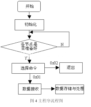
The host program includes measurement and control subroutine, communication subroutine, data processing subroutine and so on. The data measurement and control subroutine is used to control the lower computer for measurement. The communication subroutine sends control commands and receives measurement data according to the communication protocol. The data processing subroutine realizes the preprocessing and storage of data. The host program is written in C language. The host program flow is shown in Figure 4.
3 Underwater physics data collection experiment When collecting underwater physics data, there are three kinds of 8 signals to be measured: three components of electric field, three components of magnetic field and two components of the inclination angle of the sensor on the seabed. During the actual measurement, the entire measuring body (including sensors, signal conditioning circuits, watertight containers, etc.) is placed on the seabed (about 30 meters deep), and the measuring body is 120 meters away from the shore receiving host. Some other experimental parameters are set as follows: the transmission baud rate is 1Mbps, the sampling frequency of each node is 10KHz, and every 4 signals are sampled to send data to the host, each time 4 sets of 8-byte data are sent out, resolution: 0.0495μA / m ; Signal input range: -50mV ~ 50mV; Signal frequency bandwidth: 500Hz ~ 800Hz; Power supply voltage: ± 5V, 9V, ± 15V. The measurement system starts working at 9:00 am under more complicated marine environmental conditions, without stopping in the middle, and the measurement is completed by 5:00 pm. The analysis of the measurement results coincides with the theoretical calculations, which shows that the system is stable and reliable. In addition, the cost of a full set of measurement system hardware equipment (including computers and sensors) is less than 30,000 yuan.
4 Conclusion
The CAN bus has been recognized as one of the most promising fieldbuses, and it has been widely used in some high-end automotive vehicle systems. It is also gaining more and more outstanding advantages due to its high performance price ratio and simple implementation. The favor of R & D personnel. The innovation of this paper is to propose a remote data acquisition system method based on CAN bus structure. The CAN bus technology is applied to industrial field control. The hardware circuit and software are designed and applied in practice. The system can realize the real-time collection and transmission of 8 sensor signals in a complex ocean. Experiments show that the system has the advantages of simple structure, reliable performance, long transmission distance and low price. The system design method can also be applied to other multi-node systems that require data acquisition
High brightness, the light source is made of imported ultra-high brightness LED series, 120LED / m or 144LED / m encryption arrangement is the fundamental guarantee of the overall luminous effect and high brightness.
DIP & SMD LED lamps are options for different application.
Baiyang LED flex neon sign is widely used in shop,restaurant,home decoration,events as image wall,window sign,directional sign,brand logo,door head and gifts.send us the artwork and dimension.you are ensured to enjoy the unique private custom experience
Neon Letters,Led Alphabet Letters,Led Light Up Letters,Custom Led Letters
Shenzhen Oleda Technology Co.,Ltd , https://www.baiyangsign.com