Implementation of TCP / IP protocol on AT91RM9200
Abstract: The hardware interface circuit design and driver development of AT91RM9200 [1] chip and DM9161E [2] are introduced. On this basis, the TCP / IP [3] layered implementation method is discussed, and simplified according to the actual situation. Finally, TCP is discussed in detail
The specific implementation process of the / IP protocol on AT91RM9200.
Keywords: TCP / IP protocol; AT91RM9200;
Implement TCP / IP Protocol In AT91RM9200
Lin YunBiao1 Wu Chengke1 Li Yunsong1
(School of CommunicaTIon Engineering, NaTIonal Key Lab. Of Integrated Service Networks, Xidian University., Xi'an 710071, China)
Abstract: This Paper firstly introduces the design of the hardware interface circuit of The At91RM9200 and DM9161E, and then discusses how to embed the TCP / IP protocol into the AT91RM9200; Secondly, It discusses the delaminaTIon realize of the TCP / IP protocol, and According to the needs of the applicaTIon take some measures to simplify the protocol. Finally, it describes the process of realizing TCP / IP in AT91RM9200.
Keywords: TCP / IP Protocol; AT91RM9200;
1 Introduction With the rapid development of the Internet, people's demands on the network are also increasing. Especially with the development of integrated circuits like ARM [7] low power consumption, multi-function chips continue to appear. People naturally demand to realize the Internet function on them, so that their application fields become more extensive. This article uses the AT91RM9200 ARM chip design of ATMEL and the hardware interface circuit of DM9161E, and implements the TCP / IP protocol on AT91RM9100, so that it has the Internet access function, and finally can realize online data services with other devices.
2 Chip Introduction AT91RM9200 is a chip-on-chip system based on AT920T processor introduced by ATMEL Company, which integrates a wealth of standard interfaces, including USB master / slave device interface, serial port, 10 / 100M Ethernet media access controller, SPI, TWI [1], extended bus interface (EBI [1]), etc. AT91RM9200 embedded Ethernet controller can work in half duplex or full duplex mode at 10M / 100Mbps. In half-duplex mode, the controller supports IEEE802.3 CSMA / CD protocol; in full-duplex mode, it supports IEEE802.3 MAC control layer with flow control. The MAC layer of the Ethernet controller supports MII [1] (Media Independent Interface) and BDI [1] (Buffered DMA Interface), MII complies
Follow the media independent standard of ISO / IEC802.3 where the physical layer and MAC layer are separated. The physical layer interface (PHY) completes the encoding and decoding of all input and output data: 10Base-T uses Manchester encoding, 100Base-X uses 4B / 5B encoding, and 100Base-T4 uses 8B / 6T encoding. When receiving data, MII receives the original data packet with CRC added at the prefix and at the end. When sending data, MII adds a prefix and CRC at the end to the packet, and the MAC layer also generates padding data and passes it to the PHY.
DM9161E is a physical layer transceiver launched by DAVICOM that can work at 1000BASE-TX and 10BASE-TX. In terms of media, it provides an interface directly with unshielded Category 5 twisted pairs. Through the MII interface, DM9161E can communicate with the MAC layer of AT91RM9200.
3 Hardware design
The hardware interface circuit of AT91RM9200 and DM9161E is shown in Figure 1:
Figure 1 Hardware interface circuit of AT91RM9200 and DM9161E In this system, AT91RM9200 integrates an Ethernet controller (EMAC), DM9161E is responsible for physical layer communication, and HR901103A is responsible for level filtering and shielding of five types of twisted pair interfaces.
As shown in Figure 1, AT91RM9200 and DM9161E communicate through the RMII interface. The PA15 / EMDC and PA16 / EMDIO of AT91RM9200 are respectively connected to MDC [1] and MDIO [1] of DM9161E, so that the internal registers of DM9161E can be operated, including the configuration of DM9161E physical address and subnet mask.
PA10 / ETX1, PA9 / ETX0, PA8 / TXEN are connected to TXD1, TXD0, TXEN of DM9161E to control data transmission.
PA13 / ERX1 and PA12 / ERX0 are connected to RXD1 and RXD0 of DM9161E to receive data. AT91
RM9200's NRST connects to DM9161E RESET pin to reset DM9161E synchronously.
DM9161E's MDINT connects to the PC4 of AT91RM9200 to realize that when the DM9161E receives enough network packets, it sends a reception interrupt signal to the AT91RM9200 Ethernet controller, informing AT91RM9200 to process the received data.
Connect RXEN of DM9161E to high level, indicating that the reception is always valid. While TXEN is controlled by AT91RM9200, only data is valid.
PA11 / ECRSDV and PA14 / ERXER of AT91RM9200 are connected to RXDV and RXER of DM9161E respectively, and can monitor the status of the received data.
4 Software design
4.1 Device driver design The device driver design includes the following parts:
(1) Device initialization: In order for the DM9161E to send and receive data, its internal registers must be configured. These configurations include physical addresses and IP addresses. In order to implement the entire TCP / IP protocol, there is also a timer.
(2) Interrupt service program: Since there is no data in the network service is unknown, there must be an interrupt service program, which is responsible for processing the DM9161E to send an interrupt request to the AT91RM9200EMAC controller when receiving data packets, and analyze each data packet The packet type is sent to the corresponding upper protocol layer.
(3) Frame data transmission: In order to enable data transmission on the network, the data from the IP layer must also be framed. Add the Ethernet address of the receiving end, the Ethernet address of the sending end, the type of service, and the calibration before each data packet Check the code. Then send the framed data packet to the DM9161E send buffer, configure the corresponding send register: send packet buffer address, data packet length. After writing the length register, the DM9161E starts to send.
(4) Frame data reception: analyze the data packet sent by the interrupt service program, and if it is an ARP packet, give it to the ARP module for processing. If it is an IP packet, send the packet to the IP module for processing.
4.2 Specific implementation of TCP / IP Due to the rich memory resources of the traditional PC and multi-tasking system, the complete TCP / IP protocol can be implemented on the traditional PC. However, in the embedded system implemented by AT91RM9200, due to the limitation of memory and processing speed, it is impossible to achieve complete TCP / IP. Therefore, TCP / IP must be simplified according to the actual situation. This paper implements ARP, IP, ICMP, UDP and TCP on AT91RM9200, and simplifies them by layer (shown in Figure 2).
Implement the ARP protocol at the data link layer. The module consists of ARPRequest, ARPInput, ARPTimer. ARPRequest is responsible for the host sending an ARP request to determine the Ethernet address of the destination address when sending data to the network. ARPInput judges that the type of ARP packet is a request packet sent by another machine on the network or a response packet sent back to the machine, judges its legality and performs corresponding processing. If it is a request packet, the Ethernet address and the IP address of the destination address and the source address are exchanged, and then the check code is calculated, packaged and sent. If it is returned to the local ARP response packet, the IP address in the data packet is stored in the routing table, so that the destination Ethernet address can be queried when sending data in the future.
Realize IP agreement and ICMP agreement in the network layer. The IP module is composed of IPInput and IPoutput. IPInput is responsible for receiving IP data packets, and IPoutput is responsible for sending IP data packets. IPInput first determines whether the version number, checksum, and IP header length are correct. If it is incorrect, the data packet is discarded. On the contrary, it determines whether the destination address is the IP address of the current host.If it is not, it will look for the destination address in the routing table. If it is found, the data packet is forwarded. If the destination address is the current host IP address, the type of data packet is judged. If it is an ICMP, it is sent to the ICMP protocol layer; if it is a TCP packet, it is sent to the TCP protocol layer. IPoutput is responsible for sending IP data packets, receiving the data passed by the upper layer protocol, plus the 20-byte IP header, correctly setting the source and destination IP addresses, protocol type, calculating the checksum, and handing it to the link layer below. The ICMP protocol is responsible for transmitting error messages and other information that needs attention, and the type of information is determined by the 8-bit type field and 8-bit code field in the ICMP header. In AT91RM9200, only the echo request (type code 80) message processing is realized. After receiving the ICMP packet from the IP layer, it is judged whether the type code segment is 80. If these two fields are set to 00 (echo response), the checksum is calculated and then handed over to the IP layer to send; if not, it is discarded; thus supporting the ping function.
Implement the TCP protocol on the transport layer. It provides a reliable connection-oriented byte stream service. It is mainly composed of TCPInput, TCPOutput, TCPTimer, and TCB queues, and is simplified according to specific needs. The TCP control block TCB is implemented by a structure. Each TCB contains all the control and status information of a TCP connection. All TCBs form a doubly linked list, which is conducive to searching in all TCP connections. TCPTimer is responsible for managing various state information in the TCP protocol and refreshing each TCB state regularly. Here, only a 500ms slow timer is implemented [5]. TCPInput is responsible for receiving the TCP data packets received from the lower-level IP module, and branching according to the status information of the TCP connection and the various flag bits of the TCP header, handing over the data to the upper-layer application program of the corresponding port, and calling other functions to implement the TCP packet Response and state changes. TCPOutput is responsible for sending TCP packets.When receiving upper-layer application data, it first sends a SYN [4] frame to establish a connection with the target host three-way handshake, and then adds the TCP header to the lower-level IP module to send, and timing through retransmission The device implements functions such as timeout retransmission, continuous timer sending window detection frame, etc. After all data is sent and confirmed, it sends a FIN [4] frame, and the connection is closed by a four-way handshake. TCPOutput can also be The program call sends other TCP messages such as ACK frames and RST frames; on a PC, it is often possible to maintain multiple TCP connections at the same time; but on ARM, only one TCP connection is supported due to the limitations of ARM speed and RAM capacity; this greatly simplifies The complexity of the program also meets the actual needs.
Figure 2 TCP / IP architecture on AT91RM9200
5 Conclusion In informationization today, Internet technology provides great convenience for people's life, work and communication. It not only solves the information exchange between people, but also solves the information exchange between enterprises. Internet technology has now penetrated into electronic devices in daily life such as video surveillance. Colleagues in the information circles of various countries are paying attention to and studying the connection between electronic devices and the Internet. The research of TCP / IP protocol in the ARM network solves the problem of the connection between the ARM-based processing system and the Internet, and opens up a broader prospect for the application of ARM devices.
references:
[1] ATMEL AT91RM9200 datasheet.2003
[2] DAVICOM DM9161E datasheet.2001
[3] Douglas E. Comer. TCP / IP for Internet Interconnection (Volume 1). Translated by Lin Yao and others. Beijing Electronics Industry Press. 2001
[4] Wang Gang, edited by Lin Lizhi. TCP / IP programming based on Windows. Beijing: Tsinghua University Press, 2000
[5] W. Richard Stevens. TCP / IP Illustrated, Volume 1The Protocols. 2001
[6] Gary R. Wright, Wright Gary R., W. Richard Stevens, TCP / IP Illustrated, Volume 2: The Implementation, 2001
[7] Du Chunlei. ARM Architecture and Programming. Beijing: Tsinghua University Press, 2003
Jinghongyi PCB: PCBA, PCB Assembly , Printed Circuit Board Assembly Services Provider.
Jinghongyi PCB is a leading PCB manufacturer and assembler in China. It provides one-stop PCB Manufacturing and PCB assembly services, including PCB Prototype manufacturing, small and medium batch manufacturing, and Prototype PCB Assembly Services, Quick Turn PCB Assembly, Low Volume & Small Batch PCB Assembly, Middle Volume PCB Assembly, High Volume PCB Assembly, Turnkey PCB Assembly Service (including PCB production, component procurement, assembly, quality management, etc.), Lead Free PCB Assembly, Multilayer PCB Assembly, LED Lighting PCB Assembly with High Quality, Reasonable Price and Fast Turnover Time Ability.
What Does PCB Assembly Mean?
PCB Assembly Service in China
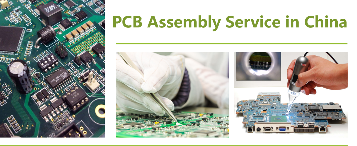
Although there are many companies in the United States, Britain, India, Australia, Canada, Mexico, Taiwan, Malaysia, Thailand, Germany, Romania and other local selection of PCB assembly manufacturers, but they are not cheaper than assemble in China, because China's PCB assembly cost is lower, better quality.
Why Choose US for PCB Assembly Services - Turnkey, Quickturn PCB Assembly Service
|
Turnkey Services |
Instant Online Quote |
Affordable Pricing |
|
Contact our online customer service or send us an email.
We offer 7*24 hours of online real-time quotation and online customer support. |
We have many years and rich experience in PCB production and assembly. There are very professional technicians and operators, with very advanced PCB assembly process, they are the guarantee of product quality. On this basis, we can also provide you with cheaper, better quality products. |
|
Quick-Turn assembly |
100% Quality Guarantee |
Mature Capabilities |
|
Get the entire PCBA produced in 20 working days from order confirmation to dispatch, including sourcing of parts. However, if you need faster delivery time, we can do it, but you may need to pay an additional premium. |
100% quality guaranteed - free re-work if needed. All parts are sourced from reliable suppliers, and each board undergoes free visual inspection. X-ray inspection, AOI testing, In-Circuit Testing (ICT), and functional testing are also available. |
JHYPCB's assembly lines are fully compliant with IPC-A-610F, are capable of SMT, through-hole and mixed assembly, and can solder BGA and fine-pitch components from 0.38mm pitch. PCB types include rigid, flexible, rigid-flex and aluminum boards. |
|
Prototype, Small or Large Batch |
Sourcing Options |
Considerate Customer Service |
|
Whether you need prototype PCB assembly or bulk assembly, JHYPCB can cater for as little as a single piece 1 to 10000 pieces and has dedicated assembly lines for both low and high volume needs. |
We can source components from reputable distributors, or you can choose from us. These parts are cheaper and can reduce the entire PCBA production time to 7 working days. |
Every PCBA order is assigned a project manager to assist you with the order process. The engineering and assembly teams will also communicate any issues with you to ensure your order proceeds as planned. |
PCB Assembly Capabilities
-
Prototype PCB Assembly as Quick as 1 Day
Our printed circuit board assembly service is North America's leading one-stop solution for PCB and assembly under one roof; specializing in small and medium runs with fast lead-times and no minimum quantity requirements.
-
A Seamless Process from PCB fabrication to PCB Assembly
All printed circuit boards assembled by Advanced Circuits are made by Advanced Circuits and we maintain full control of the entire process so you don't have to manage multiple vendors. When you choose Advanced Circuits, you can be sure that your PCBs flow directly into our in-house Assembly Department to begin assembly without delay.
-
Assembly Types
-
Surface Mount (SMT) Assembly
We are capable of small volume SMT prototyping PCBs with both automated and manual assembly.
-
Ball-Grid-Array (BGA) Assembly
We are equipped with advanced automated BGA placement equipments as well as X-ray inspection equipments to guarantee the quality of BGA assembly.
-
Through-Hole Assembly
Components are placed by inserting leads into holes that covered with solder.Both automated and manual through-hole assembly are available.
-
Mixed Assembly
Both SMT and Through-Hole components will be placed on the PCBs.Single or double side mixed assembly is available.
-
Kit Assembly
PCB Types for Assembly
- Prototype PCB Board
- FR4/ Rigid PCB Board
- Aluminum PCB Board
- LED PCB Board
- Flexible PCB Board
- Rigid Flex PCB Board
- Solder Types
Lead-Free (RoHS compliant)
- Assembly Time
From 8 hours to 72 hours once all parts are ready
- Component Types
- Ball-Grid-Arrays (BGA) of 0.25mm pitch with x-ray testing
- Passive components as small as 01005 (0402) package
- Fine-pitch components as small as 0.38mm pitch
- Test Types
- Visual Inspection
- X-Ray Inspection
- AOI Testing
- In-Circuit Test
- Functional test
- Component Suppliers
- More than 10,000 in-stock components (OPL)
- Digikey, Mouser, TME, Element 14 and more-
- PCB Assembly Testing Capabilities Learn More
| Category | Product Function | Test Type | Test Location |
|---|---|---|---|
| MCU |
51 serial MCU AVR serial MCU ARM Cortex M0, M0+, M3 and M4 serial |
IC Programming | JHYPCB's Fab |
| General |
GPIO Functional Testing Voltage, Electricity Current, Resistance Test, etc. I2C/Uart/SPI/CAN/One Wire/SWD Temperature, Humidity, Atmospheric Pressure etc. ... |
Functional Test | JHYPCB's Fab |
| Communication |
GSM/WCDMA/LTE GNSS Bluetooth/LE Ethernet NFC 802.11/b/g/n/a/ac ZigBee Sub-1 GHz 315/433/868/915 |
Functional Test | JHYPCB's Fab |
| Monoboard Computer | BeagleBone, Raspberry Pi, etc. | Functional Test | JHYPCB's Fab |
| Certification | FCC, CE, GS, TELEC etc. | Regulatory | Accredited Third-Party Lab |
PCB Assembly Applications
 |
 |
 |
 |
|
Aerospace |
Automotive |
Biomedical |
Consumer-electronics |
 |
 |
 |
 |
|
Energy |
Industrial |
Network-computer |
Telecommunications |
PCB Assembly Manufacturing Design Tips

-
Choosing between ROHS (LEAD-FREE) or standard (LEADED) solder
RoHS is used most frequently when shipping to Europe. As RoHS and Leaded solder temperatures are different, boards must either be completely soldered with RoHS or Lead. This includes BGAs. Non-RoHS components can withstand RoHS process. Avoid mixed process; that is, mixed solder. For example, a standard HASL bare board should not use a RoHS assembly process.
-
Water Clean
Aqueous clean process uses water soluble flux during soldering. The board is cleaned using water. This process yields shinier solder joints and an overall cleaner looking PCBA, without any flux residue.Use No Clean Flux only if your PCBA has some parts (batteries, microphones, speakers, relays, etc...) that can be damaged if submerged in a water wash. No Clean Flux leaves flux residue on the finished PCBA; however, flux is non-corrosive and non-conductive.
If a few components are water sensitive, you may choose to have the PCBAs processed with water soluble flux without initially soldering the water sensitive components. Make sure include specific instructions to hand solder these few components after cleaning with No Clean Flux.
-
Silkscreen
-
Placement (X-Y) Centroid Files
If you do not send centroid files with you CAD data, we can extract them for an extra fee.
-
Shortages
-
Fiducial
-
Moisture Procedure
-
Paste Layers
-
Multi-part Assembly orders
-
Substitutions
PCB Assembly Cost
PCB Assembly Cost = PCB manufacturing cost + PCB frame test or flying probe test fees + PCB engineering cost (only for small prototype order) + Component cost (additional 5%) + SMT assembly charges + PCB assembly test cost + Box building charges + Package cost (for special application) + Logistics cost (requested)
PCB Assembly Process
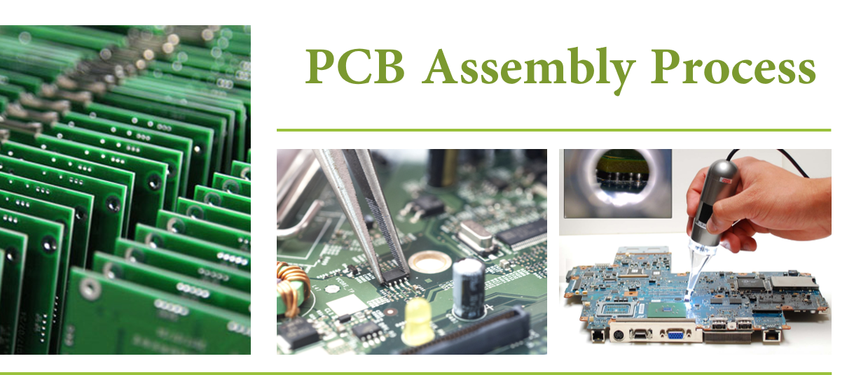
PCB Assembly Process
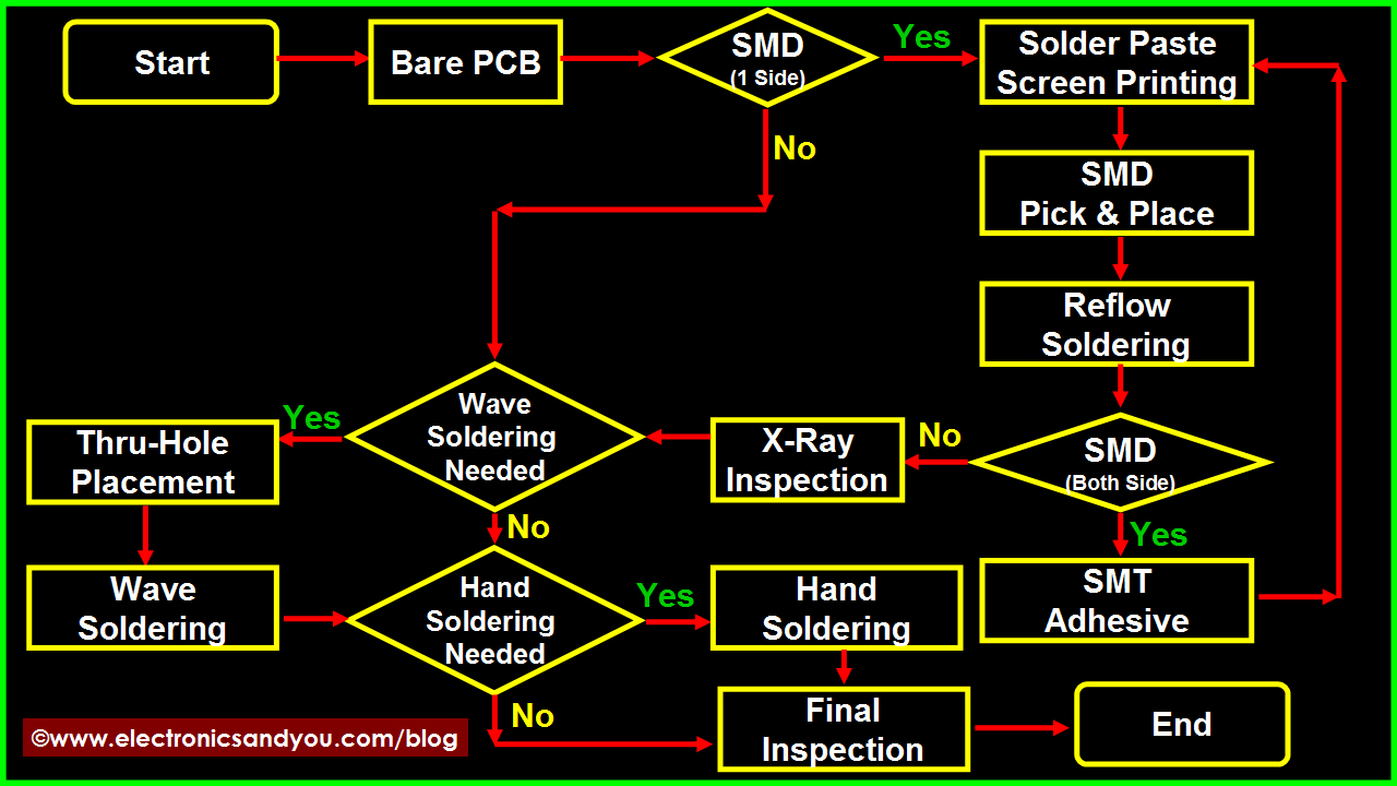
PCB Assembly Process Flow Chart
Things Needed for Printed Circuit Board Assembly
Following electronics parts and consumables are needed for PCB assembly
- Printed Circuit Board
- Electronic components
- Soldering materials including solder wire, solder paste, solder bar, solder preforms (depending on the type of soldering to be done)
- Soldering flux
- Soldering equipment including soldering station, wave soldering machine, SMT equipment, inspection and testing equipment etc.
Once all of the above equipment, electronic parts and all raw materials are arranged, it is time to start the printed circuit board assembly process.
1. PCB Manufacturing
PCB design & fabrication helps you with experienced PCB design and fabrication, high accuracy, quality control. In general, your PCB prototype can be well served by us. PCB Assembly includes layout, fabrication and assembly. We also have monthly abilities of offering 35,000 square meters PCB, 80 million point SMT and introduce ICT, flying probe, AOI, X-ray, function test, burn-in test into inspection phase. We can help you with a system of transforming natural resources, raw materials and components into a finished product that is delivered to the end customer and strive to have the most optimized supply chain to make efficient and costs lower.
2. Screen Printing of Solder Paste onto PCB Board
loctite solder pastePhysicochemical and process property of solder paste directly impact SMT soldering quality. Solder paste printing is applicable for placing appropriate amount solder paste onto PCB pads, in order to ensure good circuit connection between SMT components and PCB pads and their mechanical strength. Solder paste printing is the critical process of SMT. Metal template printing is conventionally applied so far. According to related statistics, 60%~70% quality problems are caused by solder paste printing in premise of quality guarantee of components and printed circuit board. Requirements of solder paste printing:
a. Place solder paste appropriately, evenly and uniformly. Solder paste shape is clear and neighbor shapes do not connect. Solder paste shape is in compliance with that of pad, without any dislocation.
b. In general, the unit area solder paste amount should be 0.8mg/mm2, particularly 0.5mg/mm2 for narrow-pitch components.
c. After solder paste printing, the shape has no heavy collapse and edges are trim. Plate surface is not allowed to be contaminated by solder paste.
There are a large variety of solder paste with different alloy compositions, granularity and viscosity even for all from one manufacturer. How to choose appropriate solder paste highly impacts the product quality and cost. Now NOD Electronics is using Loctite lead free solder paste. We have figured out Loctite solder paste is reliable to ensure good product quality after process engineering test of its printability, demoulding, thixotropy, cohesiveness, wettability, welding spot defect and residue.
3. Lead-free PCB Assembly
In light of environmental concerns and customer request, we can offer lead-free PCB board assembly which complies with RoHS standards. At upstream, we choose PCB laminates in compliance with RoHS standards for PCB manufacturing. Also we use lead free solder paste and related reflow/wave ovens. We strictly fulfill RoHS requirements in light of your local regulations and don`t want to make you into any trouble on this basis.
4. Burning Program and In-Circuit Test (ICT)
Our test engineers will check short circuit, voltage, current, signal transmission of PCB assembly boards according to your ICT test plan. A professional report will be handed up to you if for any detected problems. For batch order, we design exclusive test frames to fast the ICT test process. We are also well sophisticated with decoding and burning program for you. Related test frame will be built to ensure products work effectively according to your requirements.
PCB Assembly Requirement List
| No. | Types Of Assembly | File Format | Component Footprinr | Component Package | Testing Produres | Produres | Others |
| 1 | SMT ASSEMBLY | Gerber RS-274X | 0201,0402,0603- | Reels Package | Visual Inspection | Lead-Free(Rohs) | Custom Reflow Profile |
| 2 | SMT & THT Assembly | BOM(.xls,.csv,.xlsx) | BGA,QFN,QFP,PLCC | Cut Tape Package | X-Ray Inspection | Leaded Solder | Standard Reflow Profile |
| 3 | 2 sided STM,THT Assembly | Pick-N-Place/XY file | SOIC,POP...Connectors | Tube and Tray | AOI,ICT(In-Circuit Test) | Reflow Soldering | Smallest Size:0.2"x0.2" |
| 4 | Mixed Assembly | - - | Small Pitch of 8 Mils | Loose parts and bulk | Functional Testing | Wave Soldering | Largest Size:15"x"20 |
Find Out More
Flexible PCB Circuit Board Assembly
Through Hole Technology Assembly
Mixed Technology PCB Assembly
Double Sided PCB Assembly
Learn More Information
How to Mixed Technology PCB Assembly
Comparison between THT Assembly and SMT Assembly
How to start to Prototype PCB Assembly
Introduction About Single-sided and Double-sided SMT Assembly
How to ensure a smooth PCB assembly
How to Reduce PCB Assembly Cost
PCB Assembly Service
Printed Circuit Board Assembly, PCB Assembly Service, PCB Assembly
JingHongYi PCB (HK) Co., Limited , https://www.pcbjhy.com