1 Introduction
With the continuous development of automotive electronic technology and network technology, people have higher and higher requirements for automotive safety and reliability. In order to solve the communication problems caused by the increase of automotive electronic components, this requires the use of a High-speed, multi-channel, shared car communication network.
At present, a variety of buses have been developed, such as CAN (Controller Area Network) controller local area network [1], LIN (Local Interconnect Network) local area network [2], FlexRay, Most, etc. But CAN and LIN constitute the most extensive bus form on the car at present.
2 CAN bus introduction
In the late 1980s, the German Bosch company developed a serial communication protocol CAN [1] to solve the real-time data exchange between many control units and test instruments in modern automobiles, and made it an international standard (ISO11898). So far, there are more than 20 CAN bus controller chip manufacturers in the world, more than 110 CAN bus protocol controller chips and microcontroller chips that integrate CAN bus protocol controllers.
Because of its unique design and new technology, the CAN bus has outstanding reliability, real-time performance and flexibility compared with the general communication bus. CAN uses multi-master working mode, low cost, and has a very high bus utilization rate; CAN bus has a reliable error handling and error detection mechanism, using a short frame structure, short transmission time, low probability of interference; non-destructive Bus arbitration technology, the node has an automatic exit function in the case of serious errors.
3 LIN bus introduction
In 1998, Audi, Motorola, BMW, DaimlerChrysler, VCT, Volvo and Volkswagen jointly proposed a new type A bus [3-5]-LIN (Local Interconnect Network). LIN is a low-cost, short-distance, low-speed network. It is designed to transmit status changes such as switch settings and sensor inputs, and respond to such changes. Therefore, it is only suitable for low-speed events that do not require high transmission time. Not suitable for high-speed events such as engine control.
The LIN bus has its unique characteristics. It has low cost and is based on the universal UART / SCI interface; the transmission rate of LIN can be as high as 20Kb / s, and the bus length can be up to 40m; using a single master multi-slave mode, no bus arbitration is required; Self-synchronization can be achieved without the crystal oscillator and ceramic oscillator clock in the slave node: the propagation time of the deterministic signal can be calculated in advance; the node can be added or deleted on the network without changing the hardware and software of the LIN slave node.
3 Communication network design of vehicle system
The communication network of the whole vehicle system is mainly based on the CAN bus, supplemented by the LIN bus. CAN and LIN are combined with each other in the automobile communication network to jointly construct the communication network of the whole vehicle system. The various control systems on the car are sensitive to the transmission delay of network information, such as engine control, gearbox control, airbag control, ASR / ABS / ESP control, traction control, etc., which have high real-time requirements for network information transmission and require high speed CAN bus, its transmission rate is up to 500kbps ~ 1Mbps; air conditioning control, instrument control, wiper control, lighting control, door and window control, etc. need to use low-speed LIN bus, and its transmission rate is 20kbps. The low-speed LIN bus does not have high requirements for real-time information transmission, but there are a large number of subsystems. Separating these low-speed subsystems from high-speed subsystems is helpful to ensure the real-time nature of high-speed subsystems while reducing costs. Based on the above considerations, the topology diagram of the CAN / LIN bus network of the entire vehicle is shown in Figure 1.
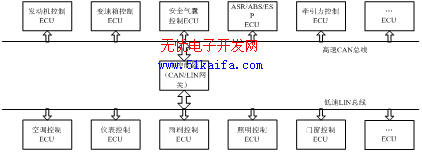
The CAN and LIN buses are independent of each other, and data sharing and data exchange are performed through the main controller (CAN / LIN gateway). The main controller is also the core of the vehicle management system. Its main function is to analyze and process various information and issue instructions, and also to coordinate the work of various control units and electrical equipment of the car.
4 System hardware and software design
4.1 CAN / LIN interface design
There are many CAN nodes and LIN nodes in the CAN / LIN network, and they realize data communication between the CAN / LIN network through a CAN / LIN interface gateway. The CAN / LIN bus interface design is shown in Figure 2. Through the CAN / LIN bus interface, CAN and LIN data can be converted between each other through the central controller. When the LIN data frame needs to be transmitted to the CAN network, the controller gateway receives the LIN bus After the data frame, the LIN identifier will be converted into a CAN identifier, so that the data is transmitted from the LIN bus to the CAN bus, otherwise the data can also be transmitted from the CAN bus to the LIN bus.
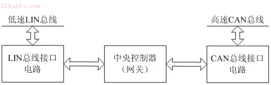
Figure 2 Automobile CAN / LIN bus network topology structure diagram
4.2 CAN communication network hardware design
Figure 3 is a schematic diagram of the CAN bus communication interface card circuit, the system uses the P87C591 chip as the main controller. The microcontroller (P87C591) of the electronic control unit is directly connected to the CAN bus controller (SJA1000) through the data bus through the photoelectric isolator (6N137). The CAN bus controller has a receive buffer and a transmit buffer. The transmit port Tx0, the receive ports Rx0 and Rx1 of the CAN bus controller are directly connected to the TxD, RxD and Vref ports of the CAN bus transmit receiver respectively. The two differential receiving and transmitting lines CAN_L and CAN_H are each connected with a 120 bus matching resistor. When the CAN bus is occupied by a node, the sending end of this node is connected to CAN_H with a level of 3.5V, and the receiving end is connected to CAN_L with a level of 1.5V. When the CAN bus is idle, the levels on CAN_H and CAN_L are both 2.5V.

Figure 3 CAN bus node circuit schematic
The system uses PCA82C250 as the interface between the CAN controller P87C591 and the physical layer bus to provide data transmission and reception to the bus. Using PCA82C250 can also improve the anti-interference ability of the system, protect the bus, reduce radio frequency interference, and achieve thermal protection.
In order to further improve the anti-interference ability of the system, the high-speed photoelectric isolation chip 6N137 is used to form an isolation circuit, and the I / O signal of the microcontroller P87C591 is isolated from the SJA1000 to improve the reliability of the system.
4.3 LIN communication network hardware design
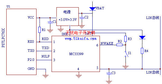
Figure 4 LIN bus node circuit schematic
Figure 4 is a schematic diagram of the LIN bus node circuit. The hardware interface circuit of the LIN node mainly includes the microcontroller P87LPC76X, the LIN transceiver MC33399 and the power supply adjustment circuit. P87LPC76X adopts 80C51 accelerated processor structure, and the instruction execution speed is twice that of standard 80C51MCU. The microcontroller sends data from TX0 to TXD of MC33399, and RXD of MC33399 sends data to RX0 of microcontroller. This circuit adopts Wake pin input switch wake-up mode, in which 5V external voltage regulator is controllable. Since the circuit integrates a resistor and a series diode between the LIN pin and the power pin, the bus slave node does not require other external components. But for the master node, you must add an external resistance, and a diode should be connected in series to prevent the MC33399 from supplying power through the bus when the battery is powered off.
4.3 CAN / LIN bus software design
The CAN communication interface module program mainly includes three parts: initialization subroutine, sending subroutine (including interrupt service routine) and receiving subroutine. When the program starts, it enters the program initialization. There are three ways to enter the initialization program: one is hardware reset; the other is software reset; the third is power-on reset. The initialization program will initialize all the message objects (all values ​​are set to 0). After the initialization is completed, the program starts to read the switch state and enter the CAN transmission subroutine. In the CAN transmission subroutine, data can only be transmitted when the transmission buffer is empty, otherwise it will wait until the transmission buffer is empty. The receiving subroutine reads the received data from the receiving buffer, and it can be received after being processed by the program.
The LIN communication interface module program also mainly includes three parts: LIN initialization subroutine, sending subroutine (including interrupt service routine) and receiving subroutine. In the initialization phase, configure the LIN transceiver and assign initial values ​​to the protocol processing variables. Like the CAN master node software sending subroutine, data can only be sent when the send buffer is empty. The central controller node is the master node of the LIN bus, and the others are slave nodes. All LIN frames are sent by the master node, and the master node is responsible for the monitoring and management of the LIN node.
4 Conclusion
At present, the CAN bus has been applied to many automobiles as a reliable automobile computer network bus, and many scholars and manufacturers in China are also researching and developing the domestic CAN bus. Compared with CAN, LIN has a lower cost and can be used as a replacement for low-speed CAN bus. It is also used in automotive bus control.
The innovation of this article: design the body network control system based on CAN / LIN bus, complete the hardware design of CAN bus and LIN bus, and the interface design of CAN / LIN gateway, and design the communication software of CAN / LIN bus.
It can be equipped with different type of storage battery such as lead acid battery, Nickel Cadmium Battery, silver zinc battery, Lithium Ion Battery and other storage batteries, providing various output voltage classes.
Built-in storage battery and charger, equipped with the function of over-charge and over-discharge protection and capacity display. It is used as working power supply for lightings, communications, laptops, and special instruments of emergency working, field working, press interviews, special vehicles and other fields.
48V Dc Power Supply,Universal Power Supply,Power Supply 500W,Electrical Load Power Supply
Xinxiang Taihang Jiaxin Electric Tech Co., Ltd , https://www.chargers.be