Abstract: An applicaTIon showing how the use of a microprocessor supervisor can be used to program a dual secTIon filter. Using the TIme delay from the reset circuit and strapping it to the power-fail comparator with a delay circuit, the filter can easily be programmed to provide the correct cutoff frequencies during power up using this reset circuit.
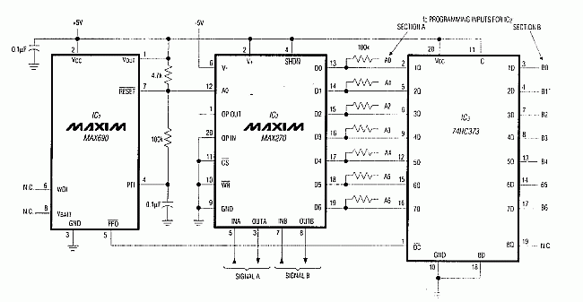
Certain dual-secTIon filter ICs have a common 7-bit port for programming the two cutoff frequencies (fC). If both sections require the same fC, you can strap an appropriate code to the port pins, but other applications require a different fC for each section. In such cases, a microprocessor is the obvious tool for sequential programming the two filter sections, but lacking a µP, you can do the job without the circuit of Figure 1.

Figure 1. A µP-supervisory chip (IC1) directs the sequential loading of fC data into the dual, programmable lowpass filter IC2. The circuit reloads this fC data following each power-up.
IC2 is a continuous, dual-lowpass filter containing identical 2nd-order sections A and B. To program desired fC values, obtain corresponding codes from the data sheet and connect each pin of A0-A6 and B0-B6 to 5V ("1" ) or GND ("0") accordingly. (The latches internal to inputs D0-D6 remain "transparent" because inputs active-low WR and active-low CS are wired low.)
Latch IC3 also remains transparent because pin 11 is wired high. The latch outputs (1Q-7Q) are three-stated when the Output Control (active-low OC, pin 1) is driven high. When active-low OC is high, therefore , A0-A6 data drives the filter port (D0-D6). When active-low OC is low, B0-B6 data appears at the latch outputs and overrides A0-A6.
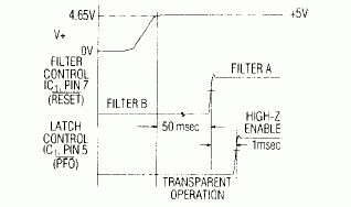
The µP-supervisory chip IC1, though normally used to monitor supply voltage and software execution in a µP system, generates directly usable signals for controlling IC2 and IC3: active-low RESET (pin 7), which remains low for 50msec after power-up , directs the input port of IC2 first to filter section A, then to section B. Active-low PFO (Power Fail Output, pin 5), which goes high in a few milliseconds after active-low RESET, provides a properly timed control signal for three-stating the latch outputs of IC3 (Figure 2).

Figure 2. Timing relationships for the Figure 1 circuit.
The circuit as shown requires ± 5V supplies. To operate on ± 2.5V or on 5V alone, connect IC1's GND pin to the lower supply rail and drive IC2's pin 12 through a resistive divider (see MAX270 data sheet, Figure 3).
Certain dual-secTIon filter ICs have a common 7-bit port for programming the two cutoff frequencies (fC). If both sections require the same fC, you can strap an appropriate code to the port pins, but other applications require a different fC for each section. In such cases, a microprocessor is the obvious tool for sequential programming the two filter sections, but lacking a µP, you can do the job without the circuit of Figure 1.

Figure 1. A µP-supervisory chip (IC1) directs the sequential loading of fC data into the dual, programmable lowpass filter IC2. The circuit reloads this fC data following each power-up.
IC2 is a continuous, dual-lowpass filter containing identical 2nd-order sections A and B. To program desired fC values, obtain corresponding codes from the data sheet and connect each pin of A0-A6 and B0-B6 to 5V ("1" ) or GND ("0") accordingly. (The latches internal to inputs D0-D6 remain "transparent" because inputs active-low WR and active-low CS are wired low.)
Latch IC3 also remains transparent because pin 11 is wired high. The latch outputs (1Q-7Q) are three-stated when the Output Control (active-low OC, pin 1) is driven high. When active-low OC is high, therefore , A0-A6 data drives the filter port (D0-D6). When active-low OC is low, B0-B6 data appears at the latch outputs and overrides A0-A6.
The µP-supervisory chip IC1, though normally used to monitor supply voltage and software execution in a µP system, generates directly usable signals for controlling IC2 and IC3: active-low RESET (pin 7), which remains low for 50msec after power-up , directs the input port of IC2 first to filter section A, then to section B. Active-low PFO (Power Fail Output, pin 5), which goes high in a few milliseconds after active-low RESET, provides a properly timed control signal for three-stating the latch outputs of IC3 (Figure 2).

Figure 2. Timing relationships for the Figure 1 circuit.
The circuit as shown requires ± 5V supplies. To operate on ± 2.5V or on 5V alone, connect IC1's GND pin to the lower supply rail and drive IC2's pin 12 through a resistive divider (see MAX270 data sheet, Figure 3).
The Industrial Relay is an automatic switching element with isolation function. It is widely used in remote control, telemetry, communication, automatic control, mechatronics and power electronics. It is one of the most important control components.
Our company's Industrial Relay are mainly devided into these three series,with good quality and most competitive price,:
1.Thermal Overload Relays
Industrial Relays,Thermal Relay,Overload Relay,Electronic Overload Relay
Ningbo Bond Industrial Electric Co., Ltd. , https://www.bondelectro.com