With the development of society, parents are paying more and more attention to the growth and development of children in infants and young children. It is necessary to invest more time and energy in caring for babies. Under the pressure of fast-paced life and work in modern society, they often feel powerless. In reality, there are too many unforeseen factors affecting the healthy growth of infants and young children. The child's body shape is at the development stage, and 70% of the time is spent in bed. In order to reduce the burden on parents during childcare and improve the quality of parenting, the functions of the common crib are simple, the performance is simple, and there is almost no intelligent detection and control. Therefore, the design of a new type of mobile crib, suitable for indoor and outdoor play, with real-time intelligent monitoring and detection of dangerous systems, can provide parents with information on the baby's living environment and activities at any time.
1 system function architecture
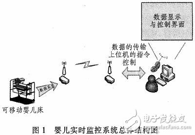
The baby real-time monitoring system mainly realizes four functions, namely data acquisition analysis and control of various sensors, transmission of wireless network, reception and monitoring of terminals, and anti-drop and anti-collision. The realization of wireless network transmission is the key of the system. . Figure 1 shows the overall structure of the baby real-time monitoring system, using the latest socket library to improve the stability and reliability of system data transmission. The Internet of Things is an important part of the new generation of information technology, and has been applied and developed in smart home systems, industry, agriculture and other industries. The basic architecture of the Internet of Things includes three aspects: the perception layer, the network layer, and the application layer. The network controller W5500, WiFi wireless router and nRF24L01 wireless technology using hardware TCPIP protocol are used as the network layer communication of the system to realize the collection and transmission of each sensor data, which has the advantages of strong stability, wide transmission range and low power consumption.
2 system modular design
2.1 Data Acquisition Module
2.1.1 Temperature and Humidity Acquisition Circuit
The design of this circuit is mainly based on the temperature sensor and humidity sensor responsible for the monitoring of the baby's real-time body temperature and whether the bedwetting is monitored. Figure 2 shows the temperature and humidity acquisition circuit. The body temperature data is a high-precision DS18B20 temperature sensor that is commonly used for temperature control, industrial systems, or thermal sensing systems for digital transmission. The DS18B20 temperature sensor contains a two-byte temperature register. The two registers can store the output data. A weak pull-up resistor is connected to the control line. By programming the registers TH and TL, the memory is improved. The accuracy and resolution of the measurement enables conversion of temperature values ​​up to 9 to 12 bits in 93.75 ms and 750 ms.
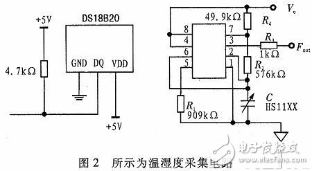
The baby is checked for bedwetting by the HS1100 humidity sensor. The HS1100 is a capacitive sensor that measures humidity based on changes in the electrical constant of the polymer material after it absorbs moisture. The A/D analog-to-digital conversion converts the output of the capacitance value into a voltage signal data that is inversely proportional to the data received by the master.
2.1.2 crying recognition circuit
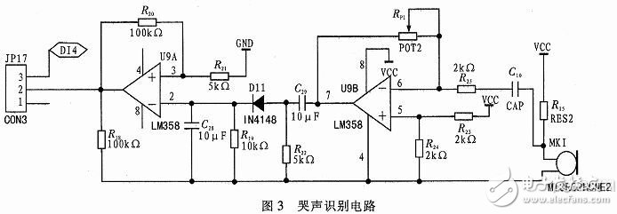
The crying recognition circuit adopts the LN567 universal phase-locked loop circuit tone decoder. The circuit design is shown in Figure 3. The MIC is used to collect the baby crying audio signal, and the MIC is acquired by the two-stage integrated operational amplifier circuit. The signal is amplified to a strong signal. The frequency of crying of babies in different situations is also different. The frequency of crying at around 15 kHz indicates that the baby is hungry. When the frequency is around 6 kHz, the baby wants to sleep. The capacitor filter circuit is used to filter the sound to reduce the interference of environmental noise. The filtered sound signal is shaped by a diode to obtain a low frequency signal, and finally the analog signal is converted into a digital signal of a sound duration by a comparator, and a pulse signal is output from the OUTPUT port of the LN567 chip to the main controller chip.
2.2 Wireless Network Module
2.2.1 WiFi transmission module
The wireless network module is designed as the main core part of the system. The data transmission between the sensors is performed through the wireless network, so that the communication wiring of each sensor in the wireless network is small, and the communication efficiency and coordination are improved. The WiFi wireless network in the system mainly realizes the transmission of video images and the driving of the baby bed motor. By swiping the WiFi control board into a highly modular, highly automated OpenWRT system based on an embedded Linux system. The camera is connected to the WiFi control board via USB, and the picked-up video image is modulated and converted and transmitted wirelessly to the upper computer to realize real-time monitoring of the baby. The WiFi control board and the main controller communicate with each other through the serial-day interface communication mode, and send the commands to the shaker motor, the toy motor, and the traveling motor through the host computer.
2.2.2 W5500 Ethernet Module
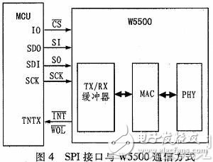
W5500 is an embedded Ethernet controller introduced by Wiznet. It realizes Internet network connection through SPI interface and supports TCP/IP protocol processing. The architecture is divided into 10/100M Ethernet data link layer (MAC) and network layer.
(NWK), Application Layer (APL), Data Link Layer and Physical Layer conform to all specifications defined by the IEE 802.3 standard. Layer-to-layer performs specific functions and related services and implements network connections through interfaces. As shown in Figure 4, the W5500 communicates with the main controller chip through the SPI serial external interface, and communicates with the host computer through the network cable. The data received by the nRF24L01 from the temperature sensor is sent to the W5500 through the wireless network. Ethernet sends the data to the machtalk server of the host computer for real-time display and recording.
2. 2.3 nRF24L01 wireless transceiver module
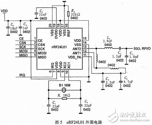
The system realizes short-range wireless communication based on the nRF24L01, an enhanced 2.4 GHz wireless transceiver based on the 8051 core produced by NORDIC. It can sense and acquire the signal of the sensor in real time and realize it by radio waves.
Data communication between sensors. After the internal A/D conversion, each sensor communicates with the digital signal through the I/O port pin and nRF24L01. The nRF24L01 packs the collected data and sends it to the receiving end. The wireless transceiver circuit is shown in Figure 5. The front end of the circuit is a radio frequency receiving module. It can be programmed by software to set its working mode (receive, idle, shutdown), connect to the main controller chip through SPI interface for data communication, and set the address code. Multi-slave data communication to the host.
2.3 system main controller module
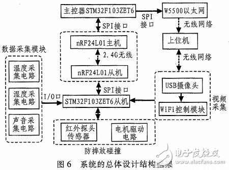
The STM32 series of microcontrollers with embedded ARM cores have the advantages of high performance, resources and rich instructions. The main control module of the baby real-time monitoring system adopts STM32F103 ZET6 processing chip based on Cortex-M3 core, which is integrated by STMicroelectronics. 64 KB SRAM and 512KB FLASH, with CAN and USB bus, 5 USART serial communication interfaces, 3 SPI bus interfaces and other circuit interfaces, to meet a variety of simultaneous communication functions, fast processing, powerful, external interface Rich, the internal data storage space has a large capacity, which can well realize the functional design requirements of the system. The overall design structure of the system is shown in Figure 6.
4 layer PCB Board
Storm Circuit Technology Ltd , https://www.stormpcb.com