Figure 5-29 shows the correspondence between the ladder diagram and the function table diagram designed by the conversion-centered programming method. In order to realize the conversion corresponding to Xi in the figure, two conditions must be satisfied at the same time: the pre-step is the active step (Mi-1=1) and the conversion condition is satisfied (Xi=1), so the normally open contact of Mi-1 and Xi is used. A circuit composed in series is used to indicate the above conditions. When both conditions are met, when the circuit is turned on, two operations should be completed: changing the subsequent step to the active step (set the Mi with the SET Mi instruction) and changing the previous step to the inactive step (using The RST Mi-1 instruction resets Mi-1). There is a strict correspondence between this programming method and the basic rules of conversion implementation. When it is used to compile ladder diagrams of complex function table diagrams, it can better show its superiority.
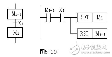
Figure 5-29 Conversion-centric programming
Figure 5-30 shows the timing diagram, function table diagram and ladder diagram of a signal control system. At the initial step, only the red light is on. Press the start button X0. After 4s, the red light is off and the green light is on. After 6s, the green light and yellow light are on. After 5s, the green light and yellow light are off and the red light is on. In a chronological order, divide a work cycle into 4 steps and use timers T0 to T3 to time 3 segments. When starting the user program, the initial step M300 is set with the normally open contact of the M8002. After the start button X0 is pressed, the normally open contacts of M300 and X0 in the second row of the ladder diagram are turned on, the M301 corresponding to the subsequent step of the conversion condition X0 is set, and the auxiliary relay M300 corresponding to the previous step is reset. After M301 changes to the "1" state, control Y0 (red light) is still "1" state, the coil of timer T0 is energized, and after 4s, the normally open contact of T0 is turned on, and the system will change from step 2 to step 3. ,So on and so forth.
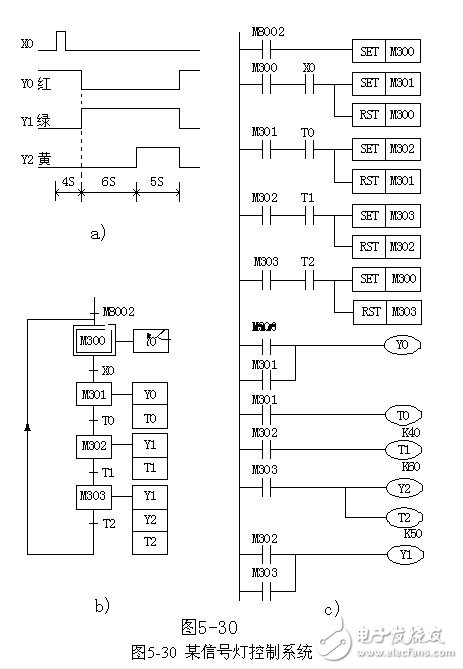
a) Timing diagram b) Function table diagram c) Ladder diagram programmed with conversion as the center
When using this programming method, the coil of the output relay cannot be connected in parallel with the SET and RST commands. This is because the time of the series circuit corresponding to the previous step and the conversion condition in Figure 5-30 is quite short, and the conversion condition is satisfied. The post-previous step is immediately reset, the series circuit is turned off, and the output relay coil should be turned on at least for the entire time of a certain step of activity.
Low-Voltage Motor,Automotive Industry Pump Motor,Oil Pump Motor,Hydraulic Pump Motor
Shaoxing AnFu Energy Equipment Co.Ltd , https://www.sxanfu.com