Abstract: For LVDS serial / deserializers with multi-channel inputs such as the MAX9209 / MAX9222, it is an effective method to measure the delay margin of the receiver to determine their jitter tolerance. Although some documents give a definition of the delay at the receiving end, there is no accepted test method. This article introduces the detailed test method of delay margin. The content provided in this article helps to understand the specifications and definitions of the delay margin given in the data sheet of the 4-way SerDes device.
The following test will give the steps in the test. The test uses Maxim's MAX9209 / MAX9222 serializer / deserializer (SerDes), works in DC equalization mode, and the connection is a 10 meter shielded twisted pair. The whole test process used Tektronix CSA8000 sampling oscilloscope, Tektronix P6248 FET differential probe, PRBS random code data.
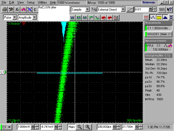
Step one measures the jitter peak-to-peak value of the differential signal at the 0V position of the rising edge of RxCLKIN, which we call Tjclk (Figure 1).

Figure 1. Measuring clock jitter at 0V differential voltage
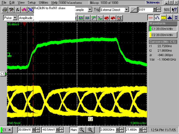
Step 2: At the input of the MAX9222, measure the time difference (deviation) between the rising edge of RxCLKIN and the leading edge of the DCA bit stream of each LVDS channel (please refer to Figure 10 in the MAX9222 data sheet) to obtain three measured values, which are called Tsk0 and Tsk1 , Tsk2 (see Figure 2).
These deviations must be tested at the jitter midpoint of RxCLKIN and the jitter midpoint of each LVDS data input. Ideally, the rising edge of RxCLKIN is aligned with the DCA data bit. Deviation refers to the deviation from the ideal state. This deviation is mainly due to the difference in the transmission distance of the LVDS channel.

Figure 2. Deviation between clock and data measured from the MAX9222 serializer
Step 3: Measure the peak-to-peak jitter of each LVDS serial data bit at the value of 0, and call it RxIN0, RxIN1, RxIN2 (please refer to Figure 13 in the MAX9222 data sheet).
The PRBS code generated by MAX9209 needs to be used in the test. In order to obtain the PRBS code, pin 14 and pin 27 of MAX9209 are pulled low, and the clock signal is connected to TxCLKIN of MAX9209. You can also choose to use movie video or complex test templates for rough verification.
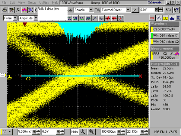
You will get 27 test results and mark them as Tjd1-Tjd27. To speed up the test, only a few bits with higher jitter peaks will be clearly observed and the results measured (see Figure 3).

Figure 3. Data jitter test
Step 4 finds the data with the largest jitter among Tjd1-Tjd27, which is called TjdL.
Step 5 Find the value with the largest deviation in Tsk0, Tsk1, Tsk2, called TskL.
Step 6 In order to meet the specification requirements for deviation margin (RSKM in the MAX9222 data sheet), the following formula must be satisfied:
RSKM ≥ (TjdL / 2) + ((Tjclk / 2)-75ps) + TskL
75ps is half of the maximum 150ns pulse position change of the MAX9209 serializer (please refer to Note 6 in the MAX9222 data sheet).
The test methods involved in this article are consistent with the specifications, pictures, and related instructions given in the MAX9222 data sheet.
The following test will give the steps in the test. The test uses Maxim's MAX9209 / MAX9222 serializer / deserializer (SerDes), works in DC equalization mode, and the connection is a 10 meter shielded twisted pair. The whole test process used Tektronix CSA8000 sampling oscilloscope, Tektronix P6248 FET differential probe, PRBS random code data.
Step one measures the jitter peak-to-peak value of the differential signal at the 0V position of the rising edge of RxCLKIN, which we call Tjclk (Figure 1).

Figure 1. Measuring clock jitter at 0V differential voltage
Step 2: At the input of the MAX9222, measure the time difference (deviation) between the rising edge of RxCLKIN and the leading edge of the DCA bit stream of each LVDS channel (please refer to Figure 10 in the MAX9222 data sheet) to obtain three measured values, which are called Tsk0 and Tsk1 , Tsk2 (see Figure 2).
These deviations must be tested at the jitter midpoint of RxCLKIN and the jitter midpoint of each LVDS data input. Ideally, the rising edge of RxCLKIN is aligned with the DCA data bit. Deviation refers to the deviation from the ideal state. This deviation is mainly due to the difference in the transmission distance of the LVDS channel.

Figure 2. Deviation between clock and data measured from the MAX9222 serializer
Step 3: Measure the peak-to-peak jitter of each LVDS serial data bit at the value of 0, and call it RxIN0, RxIN1, RxIN2 (please refer to Figure 13 in the MAX9222 data sheet).
The PRBS code generated by MAX9209 needs to be used in the test. In order to obtain the PRBS code, pin 14 and pin 27 of MAX9209 are pulled low, and the clock signal is connected to TxCLKIN of MAX9209. You can also choose to use movie video or complex test templates for rough verification.
You will get 27 test results and mark them as Tjd1-Tjd27. To speed up the test, only a few bits with higher jitter peaks will be clearly observed and the results measured (see Figure 3).

Figure 3. Data jitter test
Step 4 finds the data with the largest jitter among Tjd1-Tjd27, which is called TjdL.
Step 5 Find the value with the largest deviation in Tsk0, Tsk1, Tsk2, called TskL.
Step 6 In order to meet the specification requirements for deviation margin (RSKM in the MAX9222 data sheet), the following formula must be satisfied:
RSKM ≥ (TjdL / 2) + ((Tjclk / 2)-75ps) + TskL
75ps is half of the maximum 150ns pulse position change of the MAX9209 serializer (please refer to Note 6 in the MAX9222 data sheet).
The test methods involved in this article are consistent with the specifications, pictures, and related instructions given in the MAX9222 data sheet.
Kitchen Appliance,Small Kitchen Appliance Cooker,Counter Top Electric Cooker,Electric Hotplate Cooker
Shaoxing Haoda Electrical Appliance Co.,Ltd , https://www.hotplates.nl