introduction
As an emerging display medium, LED display is a high-tech product integrating optoelectronics and computer technology. With the rapid development of large-scale integrated circuits and computer technology, it has developed rapidly and has been widely used in various industries.
In the LED display system, most of the signals used for transmission, processing, and control are digital signals. Currently, most computers and external display devices are connected through an analog VGA interface, and digitally generated inside the computer. The image information is displayed, converted into D, G, B primary color signals and line and field sync signals by the D/A (digital/analog) converter in the video card, and the signals are transmitted to the display device through the cable. For analog display devices, such as analog CRT displays, the signal is sent directly to the corresponding processing circuit, which drives the control tube to generate an image. For digital display devices such as LCD and DLP, a corresponding A/D (analog/digital) converter is required in the display device to convert the analog signal into a digital signal.
Although there are many digital display interface products on the market, they have digital primary red, green and blue primary color signals and control signal output interfaces on the computer screen. However, most of these products have high price and sometimes compatibility. The problem, and has not yet formed a unified standard.
Therefore, as far as the analog interface is concerned, there are two main methods for obtaining data on the display screen: one is to collect data through the dedicated multimedia video card provided by the manufacturer to realize the synchronous display of the LED display screen and the computer; the second is to intercept the data. The analog signal output from the display card is used to obtain data, and the synchronous display of the LED display screen and the computer is realized. Both of these technologies already have molded products and are used in the actual work of LED displays.
For the first scheme, due to the development of science and technology will inevitably lead to the rapid update of various products, multimedia video cards will be unnecessary economic and resource waste due to continuous technological updates, and thus will be eliminated by the market. For the second scheme, since the corresponding display cards and resolution settings need to constantly change the setting parameters, the adaptability of the product is poor.
Based on the above situation, this paper proposes a new method to realize the synchronous display of LED display screen and computer, which can completely replace the multimedia video card, thus avoiding some of the drawbacks of the existing multimedia video card and achieving the integration with the international display industry standard.
2VGA conversion interface card design principle
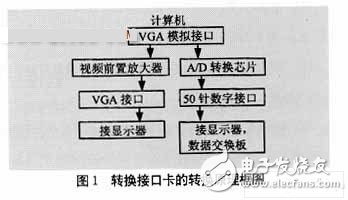
The basic working principle of the VGA conversion interface card is: using A/D acquisition technology, directly collecting image information from the general analog card analog output, no need to install a multimedia video card. Converting one analog signal into a digital signal through an A/D conversion device and feeding it into the display screen; after passing another analog signal through the video preamplifier, it is still sent back to the CRT display as an analog signal, so that the display content of the display can be The content displayed on the LED display remains consistent in real time, and the acquisition effect can be monitored at any time. The adoption of the A/D system also reduces the complexity of installation and operation. The VGA conversion interface card can be used as a peripheral of the computer to achieve "no boot installation", thereby improving the compatibility of the entire system. The structural block diagram of the principle is shown in Figure 1.
3 selection of analog to digital conversion chip
Analog-Digital Converter (ADC), as the main component of the conversion interface card, its main function is to convert the input analog quantity into a digital quantity that can be recognized by the large screen [4]. We use the AD9884A-140, a high-speed, analog-to-digital conversion device for RGB video, recently introduced by AD.
The AD9884 is a high-speed (500MHz analog bandwidth) 8-bit A/D conversion chip for intelligent VGA, SVGA, and XGA display conversion. The internal register of the chip is initialized by the microcontroller, and the predetermined working mode is written in a serial manner. After the end, the AD9884 starts working.
To use a new device, you must first understand the device's operating principle, performance specifications, limit operating parameters and typical circuit connections. If it's a smart device, learn about its programming features and parameters and get it on the market.
The analog-to-digital conversion device AD9884A is the main chip of the interface card, and other devices must be selected around the chip.
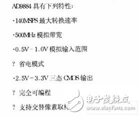
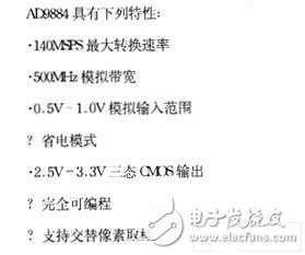
3.1 device operating characteristics
3.2 device internal structure and working principle
The AD9884A is a full 8-bit 140MSPS integrated circuit that captures RGB graphics signals from computers and workstations. Its 140MSPS encoding capability and 500Hz full-power analog bandwidth can support 1280&TImes; 1024 resolution and 75Hz refresh rate to accurately acquire and digitize each pixel.
To minimize system consumption and energy waste, the AD9884A includes an internal +1.25v voltage reference that generates a pixel clock from HSYNC, programmable gain, compensation, and clamping circuitry. The user only needs to provide a +3.3v power supply, analog input, and HSYNC signal. The tri-state CMOS output is available from a 2.5v-3.3v power supply.
The PLL phase-locked loop of the AD9884A generates a pixel clock from the HSYNC signal input. The output frequency of the pixel clock ranges from 20MHz to 140MHz. When there is no HSYNC signal, the PLL maintains its output frequency when the COAST signal is present. The AD9884A provides 32 levels of sample phase adjustment. The data, HSYNC signal, and data clock output phase relationships are always consistent. An external clock input can be used as the pixel clock instead of the PLL.
The clamp signal is generated internally or by the user via the CLAMP input pin.
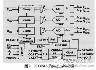
The internal structure block diagram of the analog-to-digital conversion chip is shown in Figure 2.
4 display data reception
The three RGB digital parallel signals output from the analog-to-digital conversion chip are transmitted to the display data receiving portion through the 50-pin digital output socket. The receiving part consists of the MC3486. The scanning part uses double-buffered SRAM, each of which stores one frame of data, one for receiving data writes and the other for scanning data readout. Switching is performed with the frame signal v. The data write column address is generated by the transfer clock count. The row address is generated by the row signal count. The scanning part address is generated by the crystal and the counter, and the address switching is performed by using the two-selection switch.
5 conclusions and future development direction
The VGA conversion interface card is designed to solve the current embarrassing situation of multimedia video cards and provide practical solutions for the development of display screens. No matter how the computer technology develops, the VGA conversion interface card can provide the parallel input digital signal required by the display screen. The VGA interface card has all the functions of the Galaxy multimedia card, and it has met the requirements of internationalization in terms of standardization, providing higher quality graphics signals.
The product has a high performance-price ratio and has been used in the display industry and has achieved good results.
From the development of DVI technology, we can see that the digital interface is the future development direction, which also provides a new idea for the development of LED display technology. With the popularity of DVI technology, we can send analog signals to CRT monitors through DVI-I interface compatible with analog and digital signals, while another digital signal can be sent to large screens through a series of integrations to provide large screens. Parallel digital signal. By then, LED display technology will surely enter a newer field, providing higher quality information services to all walks of life.
Big Snowflake Light,Led Snowflake Lights,Christmas Snowflake Light
XINGYONG XMAS OPTICAL (DONGGUAN ) CO., LTD , https://www.xingyongxmas.com