Abstract: This paper proposes a design and implementation scheme of network audio monitoring system based on ADI's ADSP-BF533 and network chip LAN91C111. The composition and working principle of VDK, TCP/IP stack migration, VDK-based SOCKET programming, BF533 and LAN91C111 circuit connection are introduced. Finally, the implementation method of VDK-based network communication program is given.
Keywords: digital audio; VDK; BF533; LAN91C111; SOCKET; network communication
0 Introduction In recent years, digital audio surveillance systems have developed rapidly in China, especially in the field of broadcasting. The system plays an increasingly important role. In addition, audio data is realized under the condition of ensuring the accuracy and real-time of audio information. Network transmission has also become a very important technology.
The system uses BF533 as the core processing chip, based on the VDX kernel of the software tool VDSP++, transplants LWIP as the main structure of the network, and realizes TCP/IP in ADSP-BF533.
On the transplant. At the same time, based on the VDK, through the development of the Socket server program, the direct data transmission between the embedded network terminal and the host computer is realized.
1 VDK composition principle VDK is actually a real-time operating system kernel with API function library, this is a small but very robust kernel, it is a part of Visual DSP products, VDK will also follow Visual DSP Make the appropriate upgrade or revision. Using the VDK is very convenient from a product maintenance point of view. The use of VDK is also small and brings additional costs. It has task scheduling and task management capabilities, and supports a total of 32 tasks. The VDK is the foundation of the entire software, and all other programs run on the Kernel. The components of the VDK mainly include threads, scheduling, signals, interrupted eye program device drivers, APIs, and so on.
The VDK works by first introducing multitasking and assigning its own stack space for each task, and then the task drier determines which task gets the kernel time. Task scheduling mainly involves three ways:
The first is the cooperative dispatching hall. This mode is the simplest scheduling mode. All threads in the system are given the same priority scheduling rights. The threads in the system occupy processor resources in the running state, and are arranged at the end of the waiting queue in the blocking state. You can also call the yield yourself. Function to make the thread exit the run state and enter the wait queue. In addition, any system call will cause the currently running thread to block.
The second is the time slice rotation scheduling method. The time slice scheduling mode gives a fixed execution time interval for each thread with the same priority. The time interval in the VDK is determined by setting the tick parameter.
The third is the preemptive scheduling method. If the waiting queue has a higher priority thread than the running thread, the running thread blocks and enters the waiting queue, waiting for the highest priority thread in the queue to obtain execution rights. This approach provides a more efficient and flexible approach to the other two approaches. For embedded programmers, the most familiar scheduling method is the "time slice rotation" method. In this way, each application only takes a short CPU time, and the user can hardly detect that they are rotating. The operating system or VDK automatically passes control of the operating system between all threads in a round-robin or time slice. The length of processor control time obtained by each thread is defined by the programmer. The priority of this mode can be assigned statically or dynamically. Static allocation means that the application has been assigned a priority when it was created. Dynamic allocation means that the priority of the program can still be changed while it is running, that is, its priority can be changed when the thread is materialized or running.
2 TCP/IP Stack Porting For TCP/IP stack porting, ADI offers a fast solution, a lightweight stack Lwip. Lwip (Light-weight Internet Protocl) is an open source TCP/IP protocol stack for embedded systems developed by Adam Dunkels et al. of the Swedish Institute of Computer Science. The main advantage of Lwip is that it can reduce its RAM usage while maintaining the main functions of the TCP/IP protocol. In general, it can run with only a few tens of kilobytes of RAM and about 40KB of ROM, which makes the Lwip protocol ideal for use in embedded systems.
The call to the Lwip stack is based on the ADI's driver model and the System Services Libraries. The Lwip stack supports basic protocols such as IP, ARP, ICMP, TCP, and UDP, and supports a standard set of BSD Socket interface functions.
3 VDK-based SOCKET programming When the application layer communicates data through the transport layer, TCP and UDP encounter the problem of providing concurrent services for multiple application processes at the same time. Multiple TCP connections or multiple application processes may need to transfer data over the same TCP protocol port. To distinguish between different application processes and connections, many computer operating systems provide an interface called Socket for applications to interact with the TCP/IP protocol to distinguish between network communications and connections between different application processes. There are three main parameters for generating a socket: the destination IP address of the communication, the transport layer protocol used (TCP or UDP), and the port number used. The original meaning of Socket is "socket". By combining these three parameters and binding to a "socket" Socket, the application layer can interface with the transport layer through the socket to distinguish communication from different application processes or network connections for data transmission. Concurrent service.
To communicate over the Internet, you need at least one pair of sockets, one running on the client side, called ClientSocket, and the other running on the server side, called erver So cket. Depending on how the connection is initiated and the destination to which the local socket is to be connected, the connection process between sockets can be divided into three steps, server listening, client request, and connection confirmation.
4 hardware circuit design
4.1 Introduction to ADSP-BF533 The ADSP-BF533 processor is a member of the Blackfin family of products. Its maximum operating frequency is up to 600MHz. The Blackfin processor core consists of two 16-bit multipliers, two 40-bit accumulators, two 40-bit ALUs, four video ALUs, and one 40-bit shifter that can handle 8-bit, 16-bit registers from the register bank. Or 32-bit data.
4.2 Introduction to LAN91C111 The ADSP-BF533 can transmit the data information collected by the DSP to the remote server through the Ethernet interface. The LAN91C111 is a 10/100M Fast Ethernet controller manufactured by SMSC for embedded products. It features programmable, CRC, synchronous or asynchronous operation with low power CMOS design and small size. .
4.3 Hardware connection between ADSP-BF533 and LAN91C111 The signal transmission connection between ADSP-BF533 and LAN91C111 is shown in Figure 1.
This article refers to the address: http://
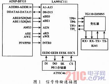
The hardware system consists of four parts: the main control chip selects ADSP-BF533, the Ethernet control chip selects LAN91C111, the network isolation chip selects TG110-E050N5, and the network port memory selects AT93C46.
Since the LAN91C111 is designed for embedded systems, its peripheral circuitry is relatively simple. Just connect the address bus A1-A15 to the system. Its A0 is not suspended by the LAN 91C111; the data buses D0-D15 are used for 16-bit data transmission. The D16-D32 on the LAN91C111 side is left floating; the chip select signal AEN of the LAN91C111 is provided by the DSP. The byte select pins BE0 and BE1 are connected to the ABE0 and ABE1 of the DSP, respectively, and the BE2 and BE3 are directly connected to the 3.3 V high voltage, that is, the 16-bit operation mode is selected. AEN is used as the chip select signal and is connected to the AMS3 pin of the DSP. The DSP chip utilizes I/O pins and interrupt pins to control and transfer data to the Ethernet controller LAN91C111 chip. The Ethernet controller LAN91C111 chip is connected to the external host computer through the network isolation chip TG110-E050N5 through RJ45 to realize data transmission. The TG110-E050N5 is a twisted pair driver/receiver with two internal coupling transformers for transmitting signals while rejecting common mode noise/interference from the media. The AT93C46 is a serial data memory. The chip uses serial transmission mode regardless of whether data is written or read. Although the serial method does not transmit in parallel, it can transfer large distance data, but it can be greatly reduced. The demand for transmission lines also reduces the overall footprint of the system. Therefore, it is very suitable for use in a microcontroller or a microprocessor.
5 VDK-based application design The main task of the network communication module in this system is to initialize the network chip and receive the emergency signal, receive the upper computer command frame and parse it, and send the selected board return instruction frame to the upper computer. .
Analysis of the above tasks, the application can be divided into three threads: one of the Boot Thread: lwip_sysboot_threadtype is to initialize the system after power-on and create each thread, then activate the Echo_Server_ThreadType thread to complete the Socket connection with the client of the host computer Secondly, the initialization thread level is the highest; after the connection is successful, the Echo_Servet_ThreadType thread activates the Echo Worker_ThreadType thread. The task of the Echo_Worker_ThreadTrype thread receives the host computer instruction frame through the recv() function and performs functional parsing, and then judges that it should be sent according to the frame function code. The frame of the host computer is ready to upload data, and then the report frame is uploaded to the host computer through the send() function and the final processing result is displayed.
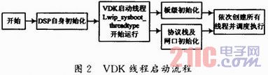
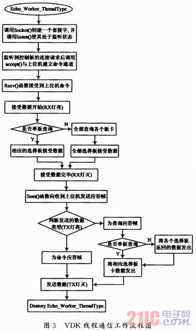
Figure 2 shows the VDK-based system threading software workflow. After the system is powered on or reset, the VDK startup thread lwip_sysboor_threadtype starts running after the DSP is started. Board-level initialization and Lwip protocol stack and network port initialization are performed in the thread lwip_sysboot_threadtype, and then the required threads are created. Figure 3 shows the communication workflow of the VDK thread.
The chip initialization module mainly performs the following tasks:
(1) System clock rate configuration: including initializing the PLL, set the stabilization time by PLL_LOCKCNT, the PLL_CTL control register sets the multiple 14 between VCO and CLKIN, and determines the clock of SCLK and CCLK by setting PLL_DIV to enable the PLL interrupt;
(2) Synchronous Serial Port (SPI) Configuration: If the SPI is enabled as a master, the SPI uses the SPI Flag Register (SPI FLG) to enable up to seven general-purpose programmable flag pins to be used as slave selects. And set to 0X02, SPISEL1 is enabled. In FIO_DIR, PF10 is set as input, and the rest are outputs;
(3) CS8420 initialization: Initialize CS8420, then the SPICTL set word length is 16 bits. When the transmit data is written to the transmit data buffer, the SPI is enabled. Set to master mode. SPI BAUD is 0x18, the baud rate is about 512b / s;
(4) Activate the Echo_Server_ThreadType thread;
(5) The destruction of the initialization thread is completed by the thread destruction module.
After the connection is successful, the Echo_Server_ThreadType thread is activated by the Echo_Server_ThreadType thread. The task of the Echo_Worker_ThreadType thread is to receive the host computer instruction frame through the recv() function and perform functional analysis on it. Determine the frame that should be sent to the host computer according to the frame function code, prepare the upload data, and upload the report frame through the send() function. Give the host computer and display the final processing result.
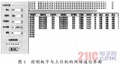
Figure 4 shows the communication results between the system control board and the host computer.
6 Conclusion In this paper, BF533 is used as the core processor, and a design scheme of VDK-based network audio communication system is proposed. At the same time, the feasibility of the scheme is verified by the operation of actual projects. Tests have proved that the system can improve transmission efficiency, and has good real-time performance and stable performance.
Barium titanate lead-free piezoelectric ceramics are important basic materials for the development of modern science and technology, which was widely used in the manufacture of ultrasonic transducers, underwater acoustic transducers, electroacoustic transducers, ceramic filters, ceramic transformers, ceramic frequency discriminators, high voltage generators, infrared detectors, surface acoustic wave devices, electro-optic devices, ignition and detonation devices, and piezoelectric gyroscope and so on.
Application: military, ocean, fishery, scientific research, mine detection, daily life and other fields.

Piezo Disc,Piezo Rod,Lead Free Piezo Rods,Lead Free Piezo Discs
Zibo Yuhai Electronic Ceramic Co., Ltd. , https://www.yhpiezo.com